
Central unit in module CP-8001 has series I. These units have the following features:
• 1 MB of memory for user programs
• 128 MB internal file system for project archiving, among others (chapter 6.9.)
• optional 128/256 KB memory for DataBox data archiving (size according to variant)
• 320 KB of memory for variables, of which 48 KB for RETAIN variables
• real time RTC circuit
• integrated Web server
• integrated Datalogger
• possibility of online change of user program (without stopping the procedure)
The mode and diagnostic messages are displayed on the integrated display.
ATTENTION! the correct numbering of the connector with the derived submodules is in this article
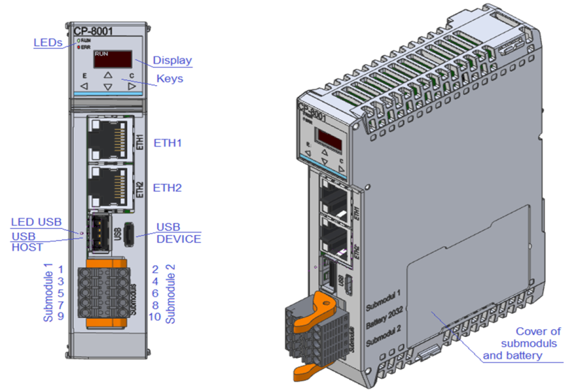
Fig. 1 CP-8001 module
Web server
The central unit contains a web server that allows you to view the status of the technology using common Internet browsers. Each page is created in XML. The Webmaker tool is used to create pages in the Mosaic development environment, which contains a graphical editor enabling the insertion of images, texts and variables from the user program in the PLC.
The files for the web server are an integral part of the PLC project and are automatically saved on the PLC's internal disk in the WWW folder. When we send a user program to the PLC from the Mosaic environment, the files for the Web server are checked at the same time, and if changes are detected compared to the files stored in the PLC, they are updated. This automatic check can be turned off in the Project Manager in the SW | node Sending files to the PLC, where we uncheck the Automatically send newer files to the PLC option.
Datalogger
The central unit contains the Datalogger service for storing variable values in a csv file. The number of Datalogger collections is 16, the number of signals in one collection is max. 16. This means that the maximum number of monitored signals is 256. Unlike TC700 systems or the first generation of FOXTROT systems, Datalogger does not create a new csv file every time the PLC is restarted , but continues to save data to the same file unless the Datalogger settings have changed. When changing the settings (for example, when adding a new signal to the collection or when changing the signal name, etc.), a new csv file is automatically created after the restart. Datalogger also now supports online program change, so there is no need to fix Datalogger variables to an absolute address in the PLC memory.
Indication elements and setting options
Indication LEDs
The central modules contain RUN and ERR LEDs, which indicate the central unit mode (see tab.2.11). LED1 indicates the status of the USB host interface and LED LTE indicates the status of the LTE interface, if equipped.
Display and buttons
The central module is equipped with a display and six buttons. In normal operation, the display shows the current PLC mode (RUN, HALT). Using the buttons marked with cursor arrows, we can scroll through other screens showing information about the PLC firmware version, ETH1 and ETH2 interface parameters, total size of available storage media and user program information (name, version and date and time of user program translation).
After switching on the PLC power supply, the parameter setting menu can be called up on the display while the PLC firmware version is displayed by holding down the keys simultaneously.
Using the buttons marked with the cursor arrows, we can choose between the offered actions. The selection is made with the (enter) button, the X (cancel) button can be used to cancel the selected action.
Interchangeable submodules
Interchangeable submodules can contain serial channels, bus interfaces or common inputs and outputs. They act essentially as additional peripheral modules connected directly to the fast ITCL internal bus.
Optional submodules are installed in the central module CP-8001 in the positions marked in Fig.2.
If additional mounting or replacement of the submodule is required, the cover at the bottom of the housing must be broken out with a screwdriver. After breaking out the lower part of the housing, the lower plate with exchangeable sub-modules is accessible. The window can then be covered with a sticker from the CP package.
 |
The modules contain components sensitive to electrostatic charge, so we follow the principles for working with these circuits! We handle only on the module without power supply! |
The submodules occupy addresses 4 and 5 on the internal ITCL bus. The submodule with address 4 is located in position 1 and is connected to the odd (left) terminals of the terminal board. The submodule with address 5 is located in position 2 and is connected to the even (right) terminals of the respective terminal block. Both submodules have a common ground on terminals 1 and 2 marked COM1. It follows that the galvanically isolated submodules are separate from the internal circuits of the central module, but not from each other.
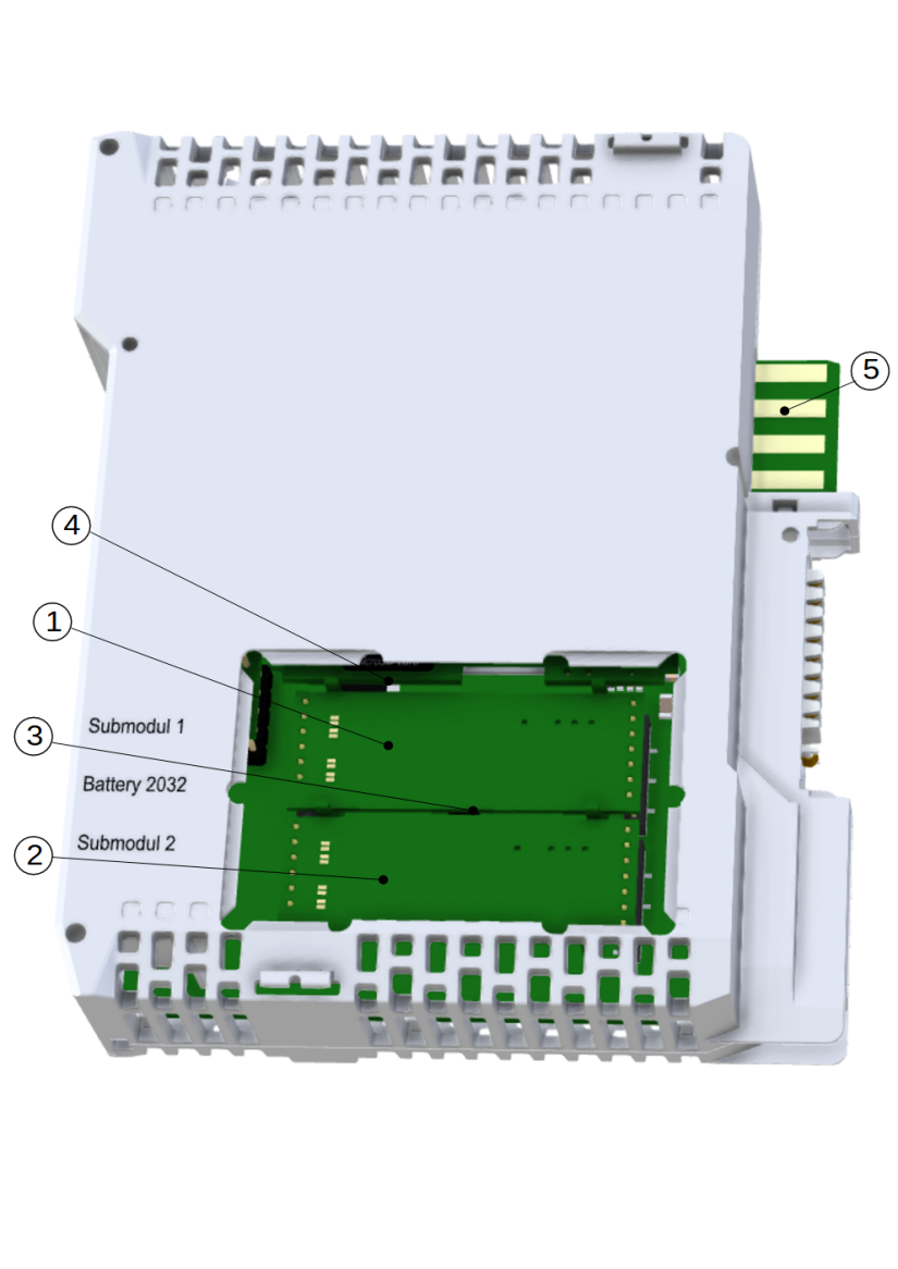
Fig. 2. Location of interchangeable submodules on the CP-8001