
Exchangeable submodules can generally contain serial channels or common inputs and outputs. They essentially act as additional peripheral modules connected directly to the fast internal bus of the base module. Modules MR-0130 to MR-0134 complement the serial communication channels on the basic module CP-8001.
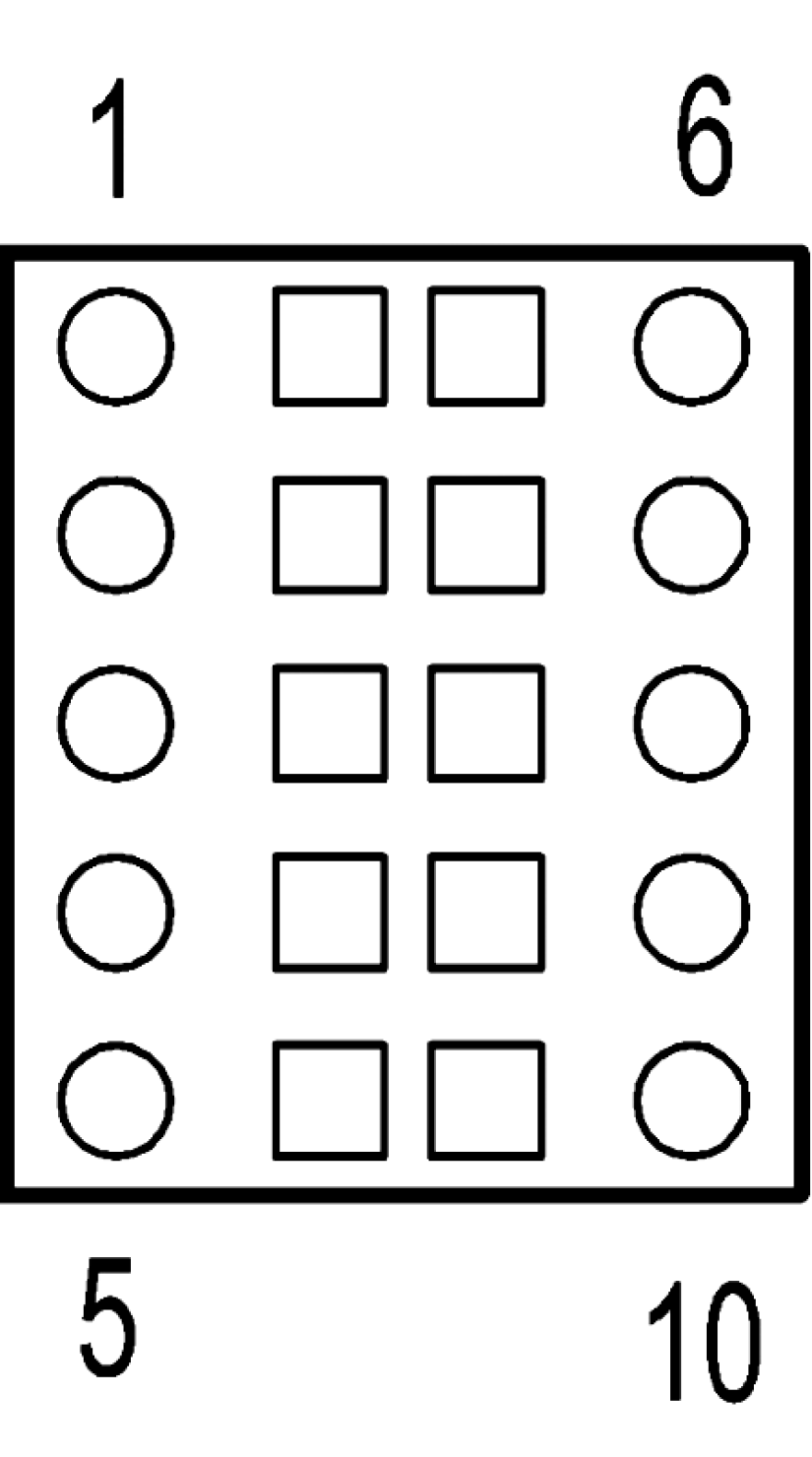
Optional submodules to the basic module, e.g. CP-8001 they mount on the right flank in the positions marked on FIg. 1.
Tab.1 Order numbers and supported modes of exchangeable submodules
| Type |
Modification |
Order number |
Supported modes |
| MR-0130 |
1x UART interface RS-232 galvanically isolated |
TXN 101 30 |
UNI |
| MR-0131 |
1x UART interface RS-485 galvanically isolated |
TXN 101 31 |
|
| MR-0133 |
2x UART interface RS-485 galvanically isolated |
TXN 101 33 |
|
| MR-0134 |
2x UART interface RS-232 galvanically isolated |
TXN 101 34 |
RS-232 and RS-485 interface parameters.
Submodules MR-0130 - MR-0134 contain serial channels of RS-232 or RS-485 interface.
For the proper functioning of the RS-485 it needs to be terminated at both ends. We perform it on the submodule by soldering the solder jumper marked BT1 (first channel) or BT2 (second channel), see picture and desription.
Connection of submodules
The submodules contain 1 or 2 serial channels with an RS-232 or RS-485 interface, depending on the selected variant. Both submodules installed in the basic PLC module have a common signal ground COM1, which is galvanically separated from the internal circuits of the PLC. The RS-485 interface on the submodules is equipped with drivers with a supply voltage of 3.3 V, which also corresponds to the level on the interface signals.
Tab.2 Connection of the CP-8001 interface connector when the MR-0130 – MR-0134 submodule is installed
|
submodule 1 |
submodule 2 |
MR-0130 |
MR-0131 |
MR-0133 |
MR-0134 |
|
 |
clamp | clamp |
1x RS-232 |
1x RS-485 |
2x RS-485 |
2x RS-232 |
|
1 |
6 |
COM1 |
COM1 |
COM1 |
COM1 |
|
|
2 |
7 |
RTS |
TxRx2+ |
TxD2 |
||
|
3 |
8 |
CTS |
TxRx2– |
RxD2 |
||
|
4 |
9 |
TxD |
TxRx+ |
TxRx1+ |
TxD1 |
|
|
5 |
10 |
RxD |
TxRx– |
TxRx1– |
RxD1 |
TxD RS-232 data transmitted
RxD RS-232 data received
RTS broadcast prompt for modem (RS-232)
CTS modem ready to transmit (RS-232)
TxRx– received and transmitted RS-485 data
TxRx+ received and transmitted RS-485 data
COM1 submodule signal ground
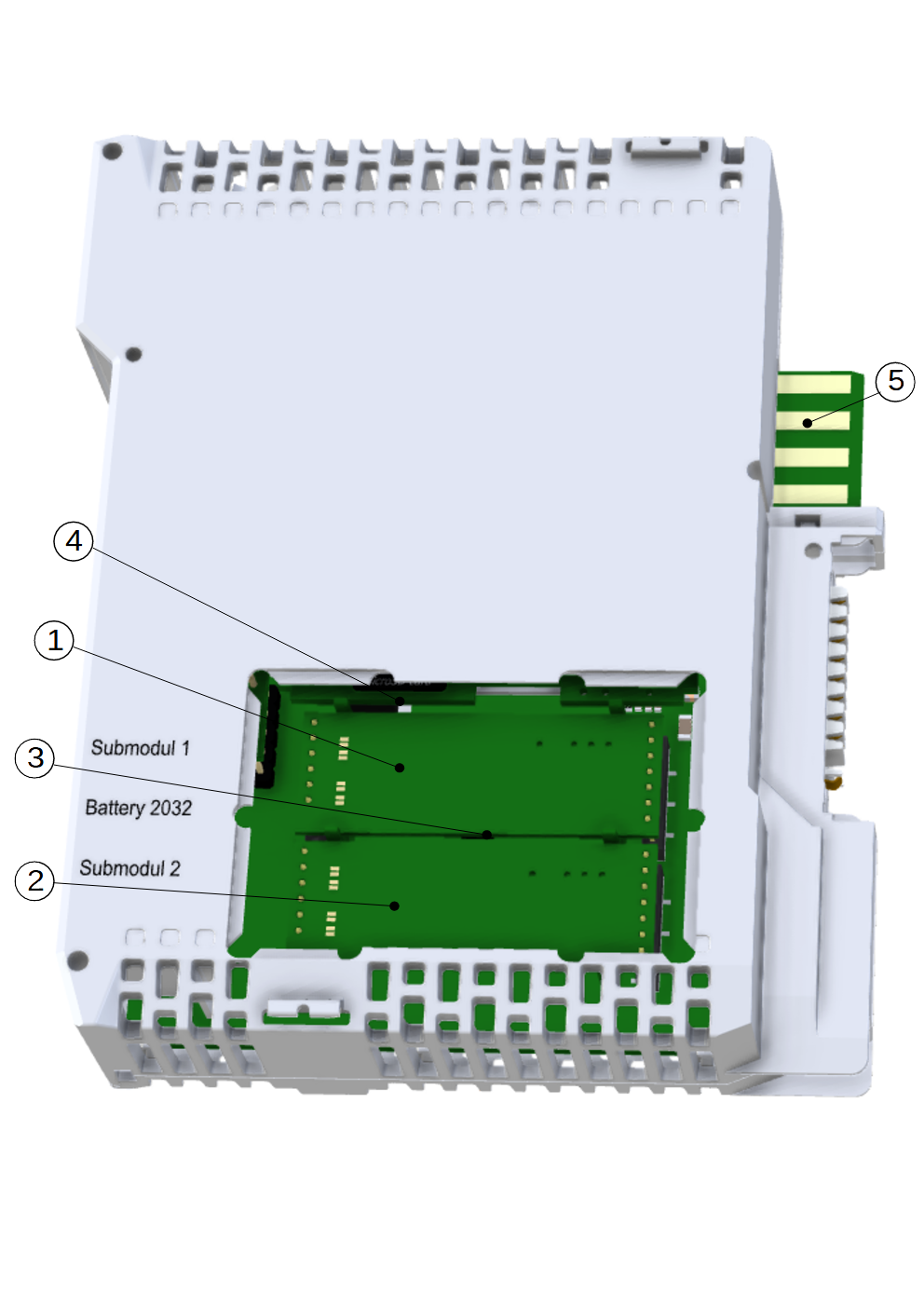
Fig. 1 Location of submodules on the side of the CP-8001
RS-485 line termination (including idle state definition) on MR-0131 and MR-0133 submodules.
In Fig. 2, there is a view of the submodule, where two pairs of flats marked BT1 and BT2 can be seen in the left part.
If we want to end the CH1 line, we have to fly through (short-circuit) the flats marked BT1 (both pairs, each separately with a drop of tin). Analogously for CH2 flats BT2. The termination on the submodule board contains not only a 150 Ω resistor between the RxTX+ and RxTX- signals, but also line quiescent definition circuitry. The circuits are powered by an internal voltage of 3.3 V.
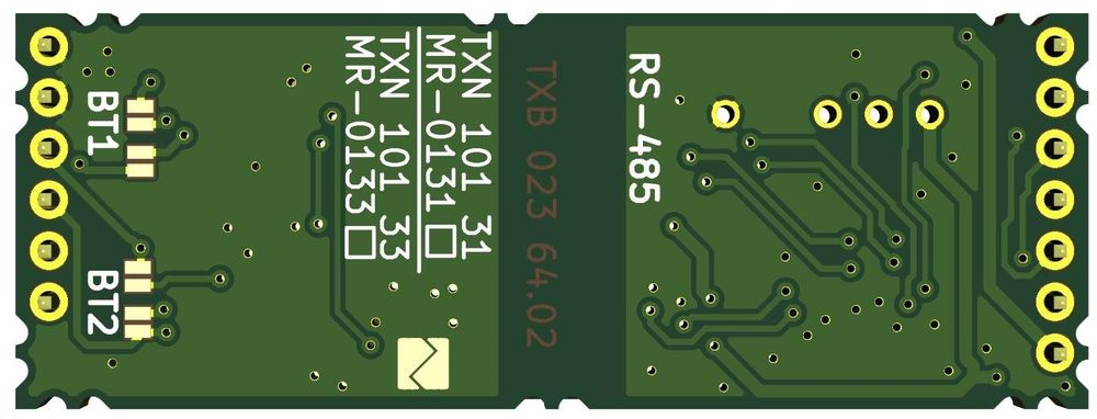
Fig. 2 Location of RS-485 line termination pads on submodule BT1 (for CH1) and BT2 (for CH2)
RS-485 line termination on MR-0131 and MR-0133 submodules delivered by September 2020:
The first series of submodules had the jumpers misplaced, the following figure 3 shows the termination of BT1 for CH1 and BT2 for CH2, in the left part it is indicated which solder pads actually correspond to channel CH1 and which to CH2 (outer BT1 for CH1, inner BT2 are terminations of channel CH2 ).
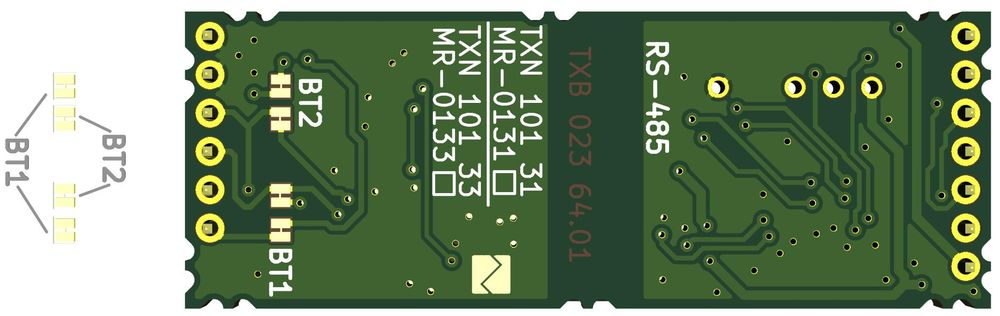
Fig. 3 Location of RS-485 line termination pads on submod valid until September 2020