
Basic description
The CP-1970 module is a complete control system of the Foxtrot series in a design intended for incorporation into the target product. The module is fully equipped with a relatively large number of inputs and outputs, including special interfaces to allow optimal configuration for the target application. Specific equipment and equipment is solved by mutual agreement with the customer.
The module is implemented as a so-called "open frame" design, ie it is not placed in any cover as standard and is ready for mounting on the base plate in the product. It is assumed to be fastened to the base plate by means of posts. More detailed data on dimensions and fastening are given in Fig. 3.
Inputs, outputs and interfaces of the CP-1970 module
The CP-1970 module is equipped with connectors to which all inputs, outputs, interfaces and power supply are connected. The connectors are marked A to M, the terminals on each connector are marked with a serial number and a connector designation, eg C1 to C7.
The specific connectors on the relevant module variant (specified by order number) are given by the variant specification (according to the agreement with the customer), so some connectors may be omitted completely or some may be shortened - eg Connector E, with terminals E1 to E7 all analog outputs are output, in case of assignment only outputs AO0 and AO1 can be shortened and only short assignment, with terminals E1 to E3.
Connector A - 230 VAC power supply
Connector B - 24 VDC power supply (in the case of power supply from 230 VAC, there is a 24 VDC output on these terminals, which can be used for powering the system's external circuits for selected variants!)
Connector C - communication interface CH1 (RS-232 or RS-485), TCL2 and CIB
Connector D - communication interface CH2 (according to the installed submodule)
Connector E - analog outputs AO0 to AO5
Connector F - analog or binary inputs AI0 to AI5
Connector G - analog or binary inputs AI6 to AI11
Connector H - analog or binary inputs AI12 to AI17
Connector I - outputs DO16, DO17, analog inputs AI19, AI20, 2x interface for sensors with communication including power supply output 5 V (only for connected sensors)
Connector J - binary input DI17
Connector K - relay outputs DO12 to DO15 (relay 5 A or SSR 1 A)
Connector L - relay outputs DO6 to DO11 (relay 5 A or relay 16 A)
Connector M - relay outputs DO0 to DO5 (relay 5 A or relay 16 A)
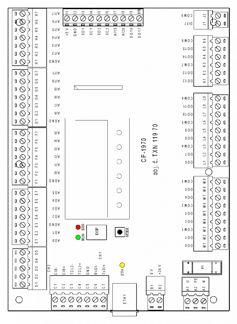
Fig. 1 Location of connectors on the CP-1970 module
Analog inputs
The CP-1970 module can be fitted with up to 20 analog inputs connected to the connectors of the AI0 to AI20 module (input AI18 is not connected to the terminals, a temperature sensor is firmly connected to it, which is needed in case of thermocouple measurement).
The inputs are divided according to possible ranges into four groups. The ranges for each input group are listed in the following table. Within the possible ranges, each input can be installed according to customer requirements.
Analog inputs AI0 to AI16 are optionally (individually for each input) also usable as binary, in which case they are defined as signals DI0 to DI16.
| Range |
AI0 ÷ AI14 |
AI15, AI161) |
AI171) |
AI19÷AI20 |
| Ni1000 |
yes |
yes | ||
| Pt1000 | yes | yes | ||
| NTC 12 k | yes | yes | ||
| resistance up to 200 kΩ |
yes |
yes |
||
| resistance up to 2 kΩ |
yes |
yes |
||
| KTY sensor (PTC) |
yes |
yes |
||
| 0 ÷ 10 V |
yes |
yes |
||
| 0 ÷ 5 V |
yes |
yes |
||
| 0 ÷ 2 V |
yes |
yes |
||
| 0 ÷ 1 V |
yes |
yes |
yes |
|
| -20 ÷ 100 mV |
yes |
yes |
||
| -20 ÷ 50 mV |
yes |
yes |
||
| 0 ÷ 20 mA |
yes |
yes |
||
| 4 ÷ 20 mA |
yes |
yes |
||
| thermocouples J, K, R, S, T, B, N |
yes |
yes |
||
| lambda probe |
yes |
yes |
||
| 0 ÷ 4 bar |
yes |
|||
| 0 ÷ 100 °C (sensor VFS) |
yes |
|||
| 1 ÷ 12 l/min (sensor VFS) |
yes |
|||
| 2 ÷ 40 l/min (sensor VFS) |
yes |
|||
| 1 ÷ 20 l/min (sensor VFS) |
yes |
|||
| 5 ÷ 100 l/min (sensor VFS) |
yes |
|||
| 10 ÷ 200 l/min (sensor VFS) |
yes |
1) Mutual combinations of ranges for inputs AI15, AI16, AI17 are given by internal mounting and it is necessary to solve them on request
Binary and counter inputs
The CP-1970 module can be equipped with up to 18 binary inputs, which are (except for the DI17 input) common to the analog inputs, and each input can be used as either analog or binary.
Inputs DI0 to DI16 can be fitted as a binary input, a potential-free contact, or a standard 24 VDC binary input with a common minus terminal.
Inputs DI8 to DI15 can also be used as counters (connection of pulse outputs of electricity meters, flow meters, etc.).
Input DI17 is a binary input 230 VAC (eg connection of an HDO signal).
| Range |
DI0 ÷ DI7 |
DI8 ÷ DI151) |
DI161) |
DI171) |
| DI (ordinary binary input 24V) |
yes |
yes |
yes |
|
| DI (pasive contact) |
yes |
yes |
yes |
|
| DI pulse input |
yes |
|||
| HDO input |
yes |
1) Mutual combinations of ranges for inputs DI15, DI16, DI17 are given by internal mounting and must be solved on request.
Analog outputs
The CP-1970 module can be equipped with up to 6 analog outputs.
Outputs AO0 and AO1 can be installed as voltage 0 ÷ 10 V, or with PWM output designed for speed control of electronically controlled circulating pumps and fans.
Outputs AO2 to AO5 are voltage 0 ÷ 10 V.
The analog outputs are connected to connector E.
PWM outputs
Analog outputs AO0 and AO1 can be installed in PWM design. The outputs are then equipped with an active 24 VDC semiconductor output with adjustable PWM repetition frequency so that they can be used to control the speed of circulating pumps or fans equipped with electronically controlled motors.
Outputs DO16 and DO17 can be used in PWM mode. Then the outputs are equipped with an active semiconductor output 24 VDC or 5 VDC (depending on the equipment) with an adjustable repetition frequency PWM so that they can be used, for example, to control the speed of circulating pumps or fans equipped with electronically controlled motors.
Binary outputs
The CP-1970 module can be equipped with up to 18 binary outputs.
Outputs DO0 to DO15 can be equipped with electromechanical relays with switching contact with max. Current 5 A / 230 VAC.
Alternatively, it is possible to install other output elements (applies to each output or pair separately):
DO0 and DO1 - instead of two 5 A relays, one 16 A changeover contact can be fitted
DO2 and DO3 - instead of two 5 A relays, one 16 A changeover contact can be fitted
DO4 and DO5 - instead of two 5 A relays, one 16 A changeover contact can be fitted
DO6 and DO7 - instead of two 5 A relays, one 16 A changeover contact can be fitted
DO8 and DO9 - instead of two 5 A relays, one 16 A changeover contact can be fitted
DO10 and DO11 - instead of two 5 A relays, one 16 A changeover contact can be fitted
DO12 - instead of 5 A relay it is possible to install SSR relay, 230 V, up to 1 A (zero switching)
DO13 - instead of 5 A relay it is possible to install SSR relay, 230 V, up to 1 A (zero switching)
DO14 - instead of relay 5 A SSR relay can be fitted, 230 V, up to 1 A (zero switching)
DO15 - instead of 5 A relay it is possible to fit SSR relay, 230 V, up to 1 A (zero switching)
DO16 and DO17 are active semiconductor outputs with a maximum output switching current of 0.5 A, each output can be equipped with a nominal voltage of 5 VDC or 24 VDC.
The outputs can be used as standard binary outputs or PWM outputs.
Outputs DO0 and DO1 are equipped with a 5 A switching contact
Output DO2 is equipped with a relay with changeover contact 16 A (in this case the second output of the pair is always unused - here DO3)
Outputs DO4 and DO5 are equipped with a 5 A switching contact

Fig. 2 Example of M connector connection
Notes:
-
The same connection (options for mounting 2x 5 A relays or 1x 16 A relays) as in the example always applies to each of the three terminals on the L and M connectors.
Special inputs and outputs
SD1, SC1, SD2, SC2
2x output serial interface, which can be connected and processed:
1) 2x RH and temperature sensor, RH: 0 ÷ 100%, T: -40 ÷ 100 ° C
2) 2x pressure sensor, 0 ÷ 250 Pa, -500 ÷ 500 Pa
Interface
The CP-1970 module can be optionally equipped with several communication interfaces:
CH1 - the first serial communication channel, optionally equipped with RS-232 or RS-485
CH2 - second serial channel - optionally interface using standard submodules
CIB - internal CIB bus master, including internal 100 mA power supply
TCL2 - TCL2 system bus master
ETH - ETHERNET interface, always installed, standard 100 Mbit, RJ-45
Power supply
The CP-1970 module can be powered from a 24 VDC source, or optionally from a 230 VAC network.
In the case of a 24 VDC supply, the supply voltage is fed to connector B (the power consumption of the module is approx. 2 to 10 W, depending on the installation).
When 230 VAC is supplied, the supply voltage is applied to connector A. The input is protected by a fuse located next to the connector. The module can be equipped with a power supply with a power of 5 W or 10 W (depending on the system, possibly according to the requirement for power supply of the module's external circuits).
In this case, connector B serves, if necessary (and according to the power reserve of the source) as a 24 V output for powering the external circuits of the system (eg power supply of a 4 ÷ 20 mA current loop, excitation of binary inputs 24 V).
Dimensions, mechanical design
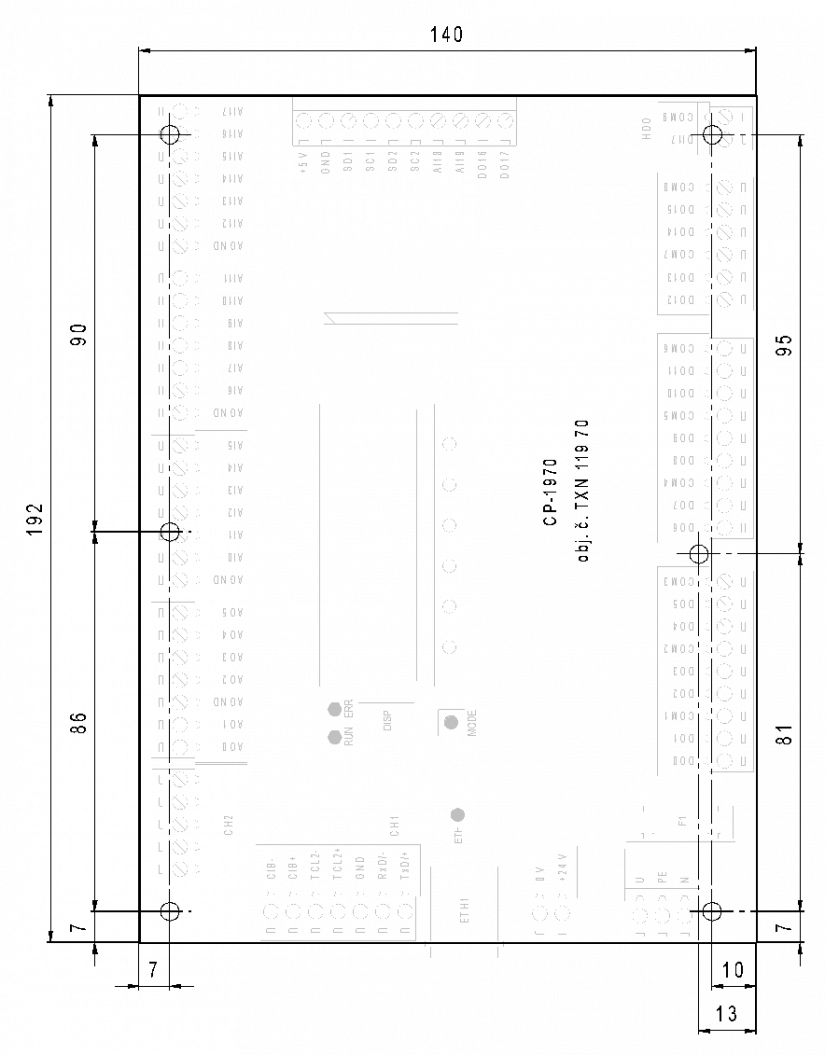
Fig. 3 External dimensions of the CP-1970 module, including the location of the mounting holes