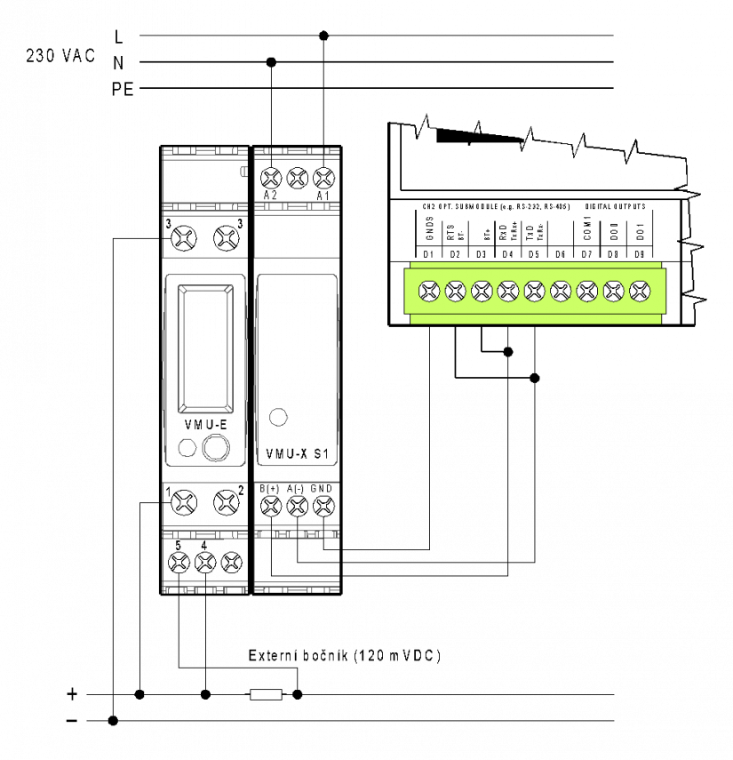
In applications with photovoltaic panels or a small wind turbine, we sometimes need to measure the DC network - DC voltage, current and power. For measuring voltage up to 400 VDC, current up to 1000 ADC we can use DC electricity meter VMU-E. The basic example of the connection of the VMU-E electricity meter with the power supply and communication module VMU-X S1 and external with a shunt, with connection to the CH2 communication interface of the Foxtrot system is shown in the following figure.

Fig. 1 Example of connection of DC electricity meter VMU-E, VMU-X S1 to CH2CP-10x6 (10x8)
Notes:
- VMU-X S1 module can be powered from a 38 ÷ 265 VAC / VDC source, the power supply is galvanically separated from other circuits, power consumption is max. 1.5 W / 3 VA.
- Both modules are connected into one unit by a side connector, each module has a width of 1M, standard design on a DIN rail.
- Indirect current measurement max. 1000 A (shunt is an optional accessory according to current), direct measurement possible (other wiring diagram) up to 20 ADC.
- The RS-485 interface is galvanically separated (4 kV insulation) from other circuits, with a cable length of up to approx. 2 meters there is no need for termination on the electricity meter side, otherwise a standard terminating resistor of approx. 120 Ω is fitted, we will use the standard cable for the RS-485 interface.
Properties and parameters of DC electricity meter, VMU-E and VMU-X S1 assembly
The electricity meter is built of two modules for mounting on a DIN rail, which are interconnected by a side connector into one unit. Assembly of measuring module (E) with source and communication module (X) enables
allows to measure direct current quantities and the amount of transmitted energy. Terminals for direct measurement up to 20 A, or auxiliary terminals for external shunt (with programmable range) for measurement up to 1000 A can be used for current measurement. RS-485 communication interface allows access to all variables: voltage, current, power and total energy , minimums and maximums of voltage, current and power.
The LED on the VMU-E module indicates:
- energy measured by flashing in red (adjustable, eg 1000 pulses / kWh).
- steady red light meets the alarm condition (this signaling has a higher priority than the indication of ongoing communication or indication of measured energy).
- zeleným blikáním probíhající komunikaci na portu RS-485
- (in the case of energy measurement and simultaneous communication, colors change).
The LED on the VMU-X module indicates the functional power supply of the device in green.
Basic technical parameters of the VMU-E and VMU-X S1 module assembly
| power voltage | 38 ÷ 265 VAC or 38 ÷ 265 VDC |
| power consumption | 3 VA / 1,5 W |
| Installation category | III (according to EN 60664) |
| Power supply of modules | galvanically isolated (4 kV), regardless of polarity |
| measured voltage | 10 ÷ 400 VDC |
| voltage measurement accuracy | ± 0,5 % of value ± 2 digit |
| input impedance (voltage measurement) | 5 MΩ |
| permanent overload | 500 VDC |
| peak overload | 800 VDC for 1 second |
| measured current (direct measurement) | 0,05 ÷ 20 ADC |
| current measurement accuracy | ± 0,5 % of value ± 2 digit |
| input impedance (direct measurement) | 0,006 Ω |
| permanent overload | 20 ADC |
| peak overload | 100 ADC for 1 second |
| measured voltage on external shunt (indirect current measurement) | 0,1 ÷ 120 mVDC |
| measurement accuracy | ± 0,5 % of value± 2 digit |
| input impedance (indirect measurement) | > 30 kΩ |
| permanent overload | 10 VDC |
| peak overload | 20 VDC for 1 second |
| communication port | RS-485 galvanically isolated (4 kV), Modbus-RTU protocol |
| operating temperature | -25 up to 55°C |
| Max. cross section of the connected wire - cable, terminals: 1, 2 | 6 mm2 |
| Max. cross section of the connected conductor - wire, terminals: 1, 2 | 10 mm2 |
| Min. cross section of connected conductor, terminals: 1, 2 | 2,5 mm2 |
| Tightening torque of the clamp screw | max. 1,1 Nm |
| Max. cross section of the connected conductor,
clamps: 4, 5, A1, A2, B(+), A(-), GND |
1,5 mm2 |
| Tightening torque of the clamp screw | max. 0,8 Nm |
