
The CP-1008 is the basic module of the Foxtrot control system. The standard version is in a 9M housing on a DIN rail (for the housing dimensions, see Chapter 13.2.1 9M housing on a DIN rail), and it is fitted with six removable terminal blocks.
I/O layout:
Power supply 24 VDC, power consumption max. 10 W (information on power supply see Chapter 2.2)
AI0 ÷ AI3 4 analogue inputs, without galvanic isolation with an optional function of a binary input:
-
ranges: Ni1000, Pt1000, OV1000, KTY81-121, binary input (potential free contact)
AI4 ÷ AI9 6 analogue inputs, without galvanic isolation with an optional function of binary input: ranges: 0 ÷ 20 mA, 4 ÷ 20 mA, Ni1000, Pt1000, OV1000, NTC 12k, NTC (measuring resistance up to 200 kΩ), KTY81-121, binary input (potential free contact)
AI10 ÷ AI11 2 analogue inputs, without galvanic isolation
-
ranges: thermocouples J, K, R, S, B, T, N, Lambda probe, voltage inputs (50 mV, 100 mV, 1 V, 2 V)
DI10 binary input 230VAC (e.g. ripple control), with galvanic separation
AO0 ÷ AO3 4 analogue outputs, without galvanic isolation, range 0 ÷10 V
DO0, DO1 2 semiconductor outputs, galvanically isolated from other circuits, 0.7 A, 230 VAC, SSR, optional PWM function
DO2 relay 5 A isolation 4 kV from other circuits
DO3 ÷ DO5 3 relay 3 A continuous current, 5 A inrush current, with a common terminal E4 (current common terminal max. 10 A)
DO6 relay, continuous current 15 A, inrush overloading 160A < 20 ms
DO7, DO8 semiconductor relay (triac output with switching at zero), max. switching current 2 A, 230 VAC, for detailed outputs wiring (in a group with DO9, DO10) see Fig. 2
DO9, DO10 electromechanical relay with a changeover contact, continuous switching current 2 A, inrush switching current 5 A; for detailed outputs wiring (in a group with DO7, DO8) see Fig. 2
ETH Ethernet 10/100 Mbit (a standard RJ-45 connector), with galvanic isolation from other circuits, see Chapter 2.4.1
CH1 Serial channel, with fixed RS-232 interface, without galvanic isolation, see Chap. 2.3.1
CH2 Serial channel, with a possibility of fitting with standard submodules, see Chapter 2.3.3
|
Binary inputs |
DI0 ÷ DI9 |
DI10 |
|
Input voltage for log. 0 |
min. +2.3 VDC max. +12 VDC |
max. 120 VAC |
|
Input voltage for log. 1 |
max. +1 VDC |
min. 200 VAC max. 250VAC |
|
Input current in log. 1 |
typically 1.7 mA |
typically 5 mA |
|
The minimum width of the captured pulse |
20 ms |
- |
|
The analogue inputs |
AI0 ÷ AI3 |
AI4 ÷ AI9 |
AI10, AI11 |
|
Temperature sensor Pt1000, W100=1.385 or 1.391 |
-90 °C ÷ +270 °C |
x |
|
|
Temperature sensor Ni1000, W100=1.500 or 1.617 |
-60 °C ÷ +155 °C |
x |
|
|
Temperature sensor KTY81-121 |
-55 °C ÷ +125 °C |
x |
|
|
Temperature sensor NTC 12k |
x |
-40 °C ÷ +125 °C |
x |
|
Resistance ranges |
0 ÷ 2 kΩ |
x |
|
|
x |
0 ÷ 200 kΩ |
x |
|
|
Current ranges |
x |
0 ÷ 20 mA 4 ÷ 20 mA |
x |
|
Voltage ranges |
x |
x |
-20 ÷ +50 mV -20 ÷ +100 mV 0 ÷ +1 V 0 ÷ +2 V |
|
Thermocouples |
x |
x |
J (–210 ÷ +1,200 °C) K (–200 ÷ +1,372 °C) R (–50 ÷ +1,768 °C) S (–50 ÷ +1,768 °C) B (+250 ÷ +1,820 °C) T (–200 ÷ +400 °C) N (–200 ÷ +1,300 °C) |
|
Lambda probe |
|
|
2.85 ÷ 21.21% O2 |
|
Input resistance for current ranges |
|
100 Ω |
|
|
Internal voltage for power supply of resistance sensors |
8.34 V |
|
|
|
Conversion time of channel |
typically 50 μs |
||
|
Recovery time of each channel value |
typically 650 μs |
||
Notes:
-
The current ranges require inserting a jumper for the relevant input. The jumpers are located under the cap with the numbers and names of terminals (above the C connector).
|
Analogue outputs AO0 ÷ AO3 |
|
|
Output range |
0 ÷ 10 V |
|
Maximum output value |
105 % of the output range upper limit |
|
Maximum output current |
10 mA |
|
Maximum load capacity |
50 nF |
|
Binary outputs, SSR |
DO0, DO1 |
DO7, DO8 |
|
Switching voltage |
max. 260 V min. 20 V |
max. 260 V min. 180 V |
|
Switching current |
max. 0.7 A |
max. 4 A |
|
With ambient temperature 25 °C |
max. 0.7 A |
IDO7 + IDO8 < 4 A 1. |
|
With ambient temperature 50 °C |
max. 0.5 A |
IDO7 + IDO8 < 2 A 1. |
|
Overload protection |
none |
Thermal protection |
Notes:
-
Maximum continuous current which does not activate thermal protection. Exceeding these values results in periodic disconnecting both outputs due to thermal protection.
-
The DO7 and DO8 outputs are connected to a group with relay outputs DO9 and DO10; for exact wiring see Fig. 2
The relay outputs:
The DO0, DO1, SSR (solid state relay) outputs with a common terminal, continuous output current 1 A, inrush 1 A, max.continuous current in common terminal COM1 is 2A. The outputs are fitted with an SSR relay switching at zero. They can be used as PWM outputs to control e.g. revolutions of small asynchronous motors (fans, circulation pumps). For more detailed information about the switching element see Chapter 13.4.5 Semiconductor relay 1 A.
Internal connection of outputs on the E connector
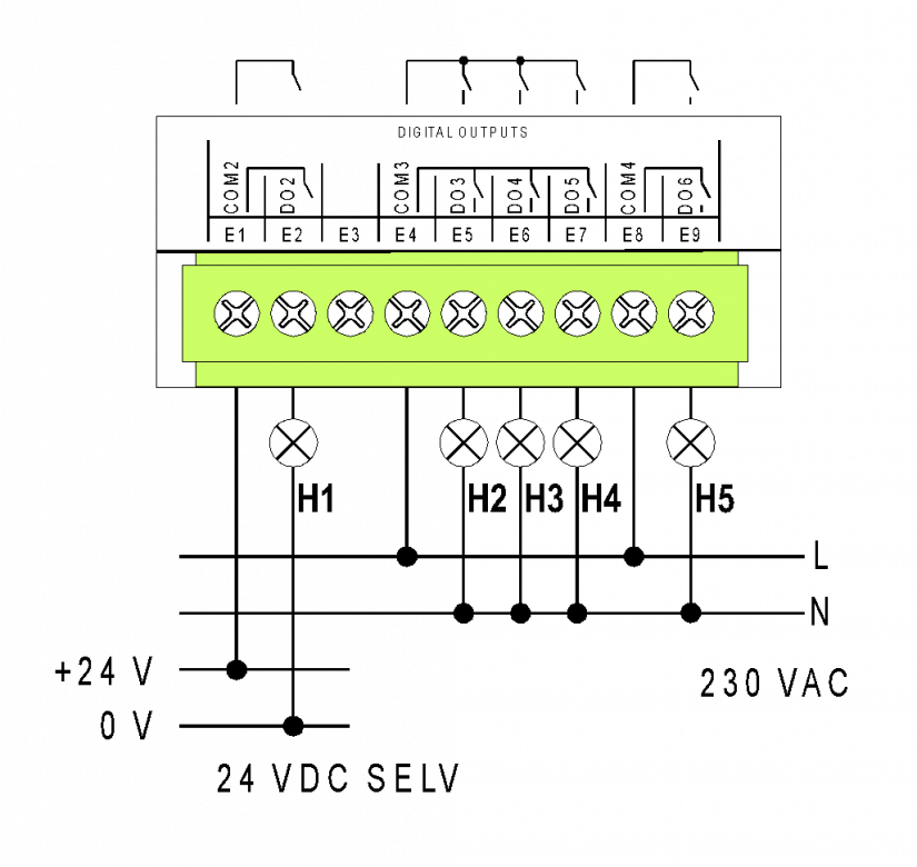
Fig. .1 An example of wiring the E connector of the CP-10x8 basic module - DO2 up to DO6 relay outputs.
The DO2 - relay, continuous 3 A output current, inrush 5 A, detailed information on relay contacts.
Isolation voltage among groups of outputs and from other circuits is 3750 VAC, i.e. safe isolation of circuits.
The DO3 ÷ DO5, outputs with a common terminal, continuous current in 3 A output, inrush 5 A, max.continuous current in common terminal COM3 is 10A, detailed information on relay contacts.
The isolation between DO6 output and the group DO3 ÷ DO5 is only the working isolation – it cannot be used for safe isolation of circuits!
The DO6 - relay continuous current 10A, inrush overloading 160 A < 20 μs, detailed information about relays in Chapter 13.4.2
Internal connection of outputs on the F connector:
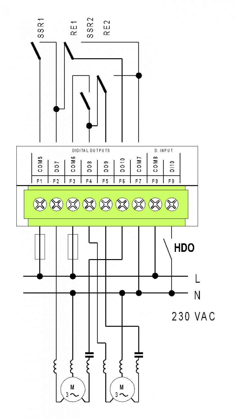
Fig. 2 An example of wiring the F connector of the CP-10x8 basic module – controlling a three-phase motor and internal wiring of the DO7 up to DO10 outputs.
The SSR1, SSR2 - semiconductor relays (triac output with switching at zero),
maximum switching current 4 A, 230 VAC.
The RE1, RE2 – an electromechanical relay with a changeover contact,
continuous switching current 2 A,
inrush switching current of 5 A, for more information on the relay see Chapter 13.4.4
The isolation voltage between the group of outputs and the input on the F connector is only the working isolation 1750VAC.
The isolation voltage between the F connector and other circuits is 3750 VAC, i.e. safe isolation of circuits
The DI10 – a 230 VAC input, ready for scanning ripple control – i.e. voltage up to 400 VAC can be connected (with improperly wired ripple control circuits).
An example of outputs wiring for controlling of three-phase motors, single-phase powered, with a possibility of reverse run. Triac outputs allow pulse control (inrush operation, speed control of e.g. a fan).
The connectors of the basic module are standard removable ones with a cage terminal in the removable part with 5.08 mm spacing. A flat-head screwdriver with the tip width of 3.5 mm is recommended for manipulation with the terminal. More detailed parameters of the terminals are specified in Chapter 13.3.1 Connectors with screw terminals, spacing 5.08mm, modules on a DIN rail

Fig. 3 An example of wiring the CP-1008 basic module