
The IC-7702 counter module is used for the connection of incremental position scanners (rotational or linear), the realization of 32 bit forward or reversible counters and other functions. The module has 4 counters. The counters (numbered 1 to 4) are divided into two pairs, which are both identical. Each pair of the counters uses 5 inputs and 2 outputs. All counters can be used in the IRC mode, the second counter from the pair (counters 2 and 4) can be additionally used for signal period measurement s. The width of the counters is 32 bits.
All counters have inputs for counting (in the reversible counter mode V - up, G - down, in the IRC mode are V and G phase-shifted signals of the stop counter) and the zero pulse (NI - in the counter mode it is used for counter clearing, in the IRC mode it is used to memorize the counted value), the counters 1 and 3 additionally have a measuring contact (MD), counter clearing (CLR) and two outputs. The outputs can be used as universal ones controlled by the program, as an output of a digital cam or for positioning. The mode of positioning can be bi-directional with one speed (the outputs control the direction of movement) or unidirectional with two speeds (the outputs control the slow and fast movement).
Counters 2 and 4 can use only two input pins that they share with the first counter from the pair. Based on their setting, their meaning is V, G (in the reversible counter mode V - up, G - down, in the IRC mode are V and G phase-shifted signals of the stop counter) or V, NI (forward counter mode, V - up, NI - counter clearing). At the G input, these counters can measure the signal period.
Assignment of input pins to counters and counter / IRC mode selection
Each pair of counters uses 5 input pins. Counters 1 and 3 are connected to all five input pins (DI10, DI11, DI12, DI13, DI14). The MD and CLR input signals are shared with the second counter from the pair (counter 2 and 4) and in case of the use of counter 2 (or 4) these signals are not available for counter 1 (or 3).
Table 8.5.1 Assignment of input terminals to counters:
|
Connector |
Meaning of signals on connector terminals according to counter mode |
||||||
|
Connector terminal number |
Connector terminal name |
Counter 1 – mode IRC or counter, with measuring contact and ext. clearing Counter 2 - unused |
Counter 1 – mode IRC or counter Counter 2 – IRC or reversible counter without ext. clearing |
Counter 1 – mode IRC or counter Counter 2 – forward counter with ext. clearing |
Counter 3 – mode IRC or counter, with measuring contact and ext. clearing Counter 4 - unused |
Counter 3 – mode IRC or counters Counter 4 – IRC or reversible counter without ext. clearing |
Counter 3 – mode IRC or counters Counter 4 – forward counter with ext. clearing |
|
1 |
DI10 |
V1 |
V1 |
V1 |
|
|
|
|
2 |
DI11 |
G1 |
G1 |
G1 |
|
|
|
|
3 |
DI12 |
NI1 |
NI1 |
NI1 |
|
|
|
|
4 |
DI13 |
MD1 |
V2 |
V2 |
|
|
|
|
5 |
DI14 |
CLR1 |
G2 |
NI2 |
|
|
|
|
8 |
DI20 |
|
|
|
V3 |
V3 |
V3 |
|
9 |
DI21 |
|
|
|
G3 |
G3 |
G3 |
|
10 |
DI22 |
|
|
|
NI3 |
NI3 |
NI3 |
|
11 |
DI23 |
|
|
|
MD3 |
V4 |
V4 |
|
12 |
DI24 |
|
|
|
CLR3 |
G4 |
NI4 |
Each input has an independent digital filter, which suppresses unwilling interference and contact bounces. The filter can be set-up to one of the four time periods (delays):
|
Filter delay |
|
100 ns |
|
185 us |
|
1.48 ms |
|
11.85 ms |
DIxy Terminal of binary input y (from group x).
COMx Common pole of group x of input circuits of the module.
UDO Common pole of output circuits of the module (+ 24 VDC),
max. current 4 A.
COM Common pole of output circuits of the module, operational
only (necessary for function of input circuits of the outputs
of the module), max. consumption 50 mA.
DOxy Output terminal of output y (from group x)
-
Binary inputs are standard 24 VDC, common pole –
-
Binary outputs are standard 24 VDC, 2 A per an output (totally for a group of 4 max. 4 A), with common pole + (detailed parameters such as outputs of the OS-7401 module)
-
The groups (both input and output group) are galvanically isolated from each other.
-
Identically labelled terminals are interconnected inside the module.

Figure 8.5.1 Terminal connection of IC-7702 module connector

Figure 8.5.2 IC-7702 module connection example
8.5.1.1 IC-7702 counter module connection examples
Example 1 - Connection of two incremental position scanners including the evaluation of zero pulses
- Connection of contacts of the measuring contact (MD)

Figure 8.5.3 Connection of IC-7702 module according to example 1
The figure 8.5.3 illustrates the basis use in the configuration for the evaluation of two incremental position scanners. The connection assumes a scanner fed from a 24 V= source using an external 24 V power supply source. The scanner outputs are open PNP collectors (switches against positive terminal of +24 V power supply). The contact of the measuring contact is supplied from the 24 VDC source (as the standard PLC binary input).
Notes:
-
To increase resistance, a shielded supply lead should be used (JYTY, etc..), shielding of which will be connected according to general principles (see chapter 4.2.5 of the manual).
-
The incremental position scanner used has to have 24 V outputs, open PNP collector (OC PNP), or push/pull outputs.
-
The binary outputs (DO0 to DO3) can be used also as normal transistor outputs 24 V, 1 A per output.
Example 2 - Connection of 4 pulse outputs (e.g. water and gas meters, etc.), the IC-7702 module is used as 4 32 bit forward counters.
- Control of 4 external relays by module outputs.
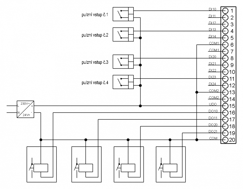
Figure 8.5.4 Connection of IC-7702 module according to example 2
The figure 8.5.4 illustrates the basis use in the module configuration as 4 forward counters. The connection assumes pulse outputs from the technology 24 V= and PNP open collector and equivalent solution (switches against the positive terminal of +24 V power supply). Possible bounces of the switches can be treated by a a digital adjustable filter on the module. All outputs can be used as standard PLC outputs.
Notes:
-
To increase resistance, a shielded supply lead should be used (JYTY, etc.), shielding of which will be connected according to general principles (see chapter 4.2.5 of the manual).
8.5.1.2 IC-7702 module outputs
The outputs can be used in various modes that can be set in the control word by the program:
-
Direct control from program (refer to example 2)
-
Digital cam mode
-
Positioning mode UP/DOWN
-
Positioning mode with slow-down modes
-
Counter mode
Detailed information on module modes can be found in the documentation TXV 004 22.