
For flow measurement and heat supply measurement in drinking water distribution systems, in solar
systems and in heating systems of water and antifreeze liquids with a maximum medium temperature of 120 ° C in the flow range 1 to 12 or 2 to 40 l / min we use the flow meter AV23. It is a flow meter using the Grundfos VFS (Vortex Flow Sensor) flow and temperature measurement module. This module is also used by other manufacturers of flow meters, which can also be used (for flow rates up to 200 l / min).
The AV23 control flow meter is designed for simultaneous measurement of medium flow and temperature. The flow is measured on the principle of vortexing in the medium.
Flow media:
- Mixtures of water with common anti-corrosion and antifreeze additives (glycol resistant)
- Heating water
- Drinking water
- Cold and hot water
The flow meter can be installed anywhere in the solar circuit (for common solar collectors max. Operating temperature 120 ° C sufficient), the most aqueous is installation on the return pipe (see fig. 2). The working position of the flow meter is arbitrary.
When installing, it is necessary to take into account the length of the supply cable approx. 110 cm. The cable is terminated with a special connector for direct connection to the C-AM-0600I module and its extension is inappropriate.
| Order number | 223.7702.000 | 223.7704.000 |
| Flow range | 1 – 12 (l/min) | 2 – 40 (l/min) |
| lightness | DN 20 | DN 20 |
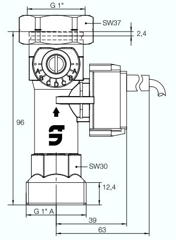
| fittings | G1" × G1" A | G1" × G1" A |
| Max. operating temperature: |
120 °C |
|
| Temperature measuring range: |
0 - 100 °C |
|
| Max. the operating pressure: |
8 bar |
|
| Flow measurement accuracy: | < 3% final values | 1.5% final values |
| Medium viscosity: |
≤ 4 mm²/s |
|
| Thread |
G (cylindrical) according to ISO 228 |
|
| Case material: | brass | |
| Material of internal parts: |
brass, stainless steel, plastic |
|
| Sensor material: |
PPS, PPA, PA |
|
| Seal material: |
EPDM |
|
| Connection |
with flat seal 1" |
|
| Degree of IP protection: |
IP44a |
|
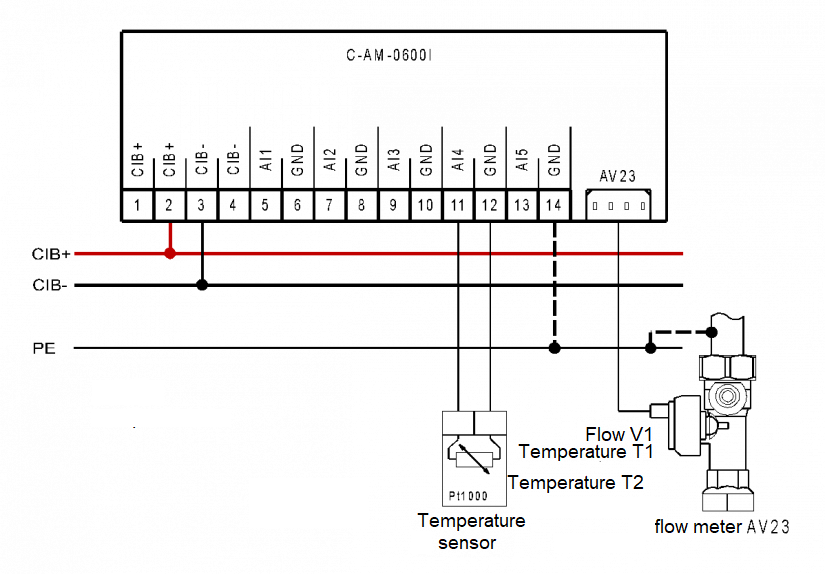
Fig. 1 Example of AV23 flowmeter / thermometer connection to C-AM-0600I module.
Note:
- The flow meter is equipped with a 110 cm long cable terminated with a connector for connection to the C-AM-0600I module.
- The valve can be installed in a horizontal, oblique or vertical position. You only need to pay attention to the direction of the arrow indicating the media flow.
- The temperature sensor can be connected to any input of the module (AI1 to AI5), for temperature measurement T2 it is possible to use a temperature sensor connected to any module in the system.
- ATTENTION! The manufacturer of the VFS (flow sensor) module recommends to ground the negative terminal of the flowmeter power supply (Fig. GND terminal of the module to ensure the stated measurement accuracy C-AM-0600I) and at the same time a pipe with a flow meter on the PE terminal. The grounding is indicated by the dashed line in the figure. This also grounds the CIB- terminal and changes the installation to PELV from the point of view of electrical safety. Beware of ground loops - the power supply of the system, including the CIB bus, must no longer be grounded at another point in the installation.
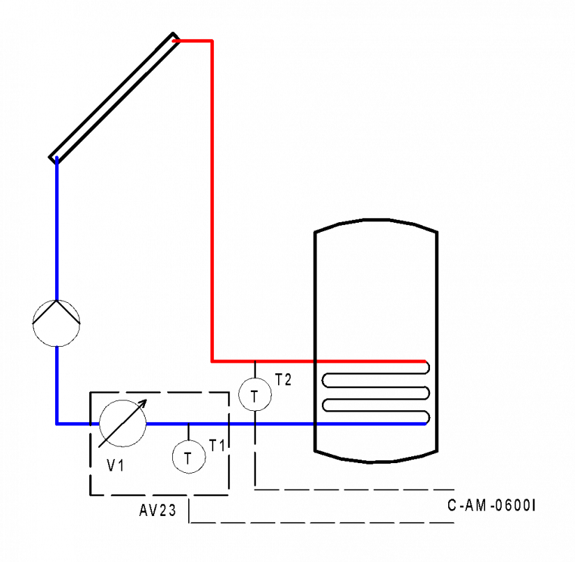
Fig. 2 Příklad umístění prvků pro měření tepla vyrobeného solárním systémem