We supply older versions only in version C-EM-0401M-P035 (35 A die-cut transformer). Other variants are replaced by a newer version C-EM-0401M-S (order no. TXN 133 22.90), in which the customer chooses suitable current transformers with a 100 mA output. It can also change them itself, the conversion constant of the transformer is entered into the configuration of the C-EM-0401 module during its operation in prog. Mosaic environment..
For fast and accurate measurement of 3f network (measurement of phase voltages, currents, active and reactive powers, power factors, THD voltages and currents and frequencies in the LV network, etc.), in the range of rated currents from 15 A to 150 A (according to the meter configuration ) we can use the electricity meter on the CIB bus C-EM-0401M. The meter is also equipped with voltage and frequency protection for controlling PV, HFVE and cogeneration units.
It is possible to order the C-EM-0401M electricity meter with other ranges of maximum measured currents (from 5 A to 600 A), with two variants of current transformers (through and opening).
Connection and measurement:
four voltage inputs (L1, L2, L3, L4) measured against the zero input (N).
The measured voltages should be secured, for example, with a 1 A fuse.
four current measuring inputs for connection of bushing (variant P) or opening (variant S) transformers with nominal current 5 A to 600 A (I1, I2, I3, I4).
The current signals of measuring transformers (selection of transformers according to the current range and method of installation is given in the following table) are connected to the pairs of terminals l1, k1, l2, k2, l3, k3, l4, k4 and their correct orientation must be observed (white wire to terminal k, the connection of the transformers is described in detail in the notes to the following connection example).
The standard supply voltage of the electricity meter is 75 ÷ 510 VAC or 80 ÷ 350 VDC.
The supply voltage of the electricity meter must be connected to terminals X1 and X2 via a disconnecting element (circuit breaker - see
following connection example). A circuit breaker with a nominal value of 1 A is suitable as a disconnecting element.
An electricity meter with a supply voltage range of 24 ÷ 48 VAC or 20 ÷ 75 VDC can be supplied on request.
The electricity meter samples 128 samples per period, sampling is controlled by the measured frequency on L1. The meter measures and evaluates voltage and current signals continuously without interruption, the basic evaluation interval is 200 ms.
In this interval, it is possible to read from the electricity meter via the bus the instantaneous values of active power (production, consumption) for each phase.
Other quantities can be read by query commands according to current needs.
In addition to voltages, currents and active powers, the meter also provides: reactive, apparent, deformation and fundamental active and reactive power, power factor, harmonics and THD currents and voltages, calculation of harmonic voltages and currents up to 63 harmonics.
The current inputs of the electricity meter must never be used for direct current measurement! Always use only the measuring transformers supplied with the device.
Electricity variants according to the current range and type of measuring transformers are listed in the following tables (always all 4 current inputs of the electricity meter have identical transformers):
Design with bushing transformers:
| Max. measured current | 15 A | 35 A | 75 A | 150 A |
| Ord. number | C-EM-0401M-P015 | C-EM-0401M-P035 | C-EM-0401M-P075 | C-EM-0401M-P150 |
| Type of measuring transformer | JP3W |
JP5W |
||
| Inner diameter of the hole for the measured conductor | 7 mm |
13 mm |
||
| External dimensions transf. | 24 x 27 x 11 mm |
37 x 41 x 14 mm |
||
Design with openable transformers:
| Max. measured current | 35 A | 75 A | 150 A |
| Ord. number | C-EM-0401M-S035 | C-EM-0401M-S075 | C-EM-0401M-S150 |
| Type of measuring transformer | JC10F | JC10F | JC16F |
| Inner diameter of the hole for the measured conductor | 10 | 10 | 16 |
| External dimensions of the transformer | 23 x 50 x 26 mm | 23 x 50 x 26 mm | 30 x 55 x 31 mm |
The C-EM-0401M electricity meter is equipped with a DO1 output, which is controlled by a protective function implemented in the electricity meter. The electricity meter implements the function of voltage and frequency protection, the range of monitored undervoltage, overvoltage, underfrequency and overfrequency, including reaction times is set in the parameters of the electricity meter. The same time is set for the resumption after the cause of the protection activation has disappeared.
…. more detailed data of the protection function will be added…
Basic technical parameters of the C-EM-0401M electricity meter
| power voltage | 85 ÷ 275 VAC / 45 ÷ 450 Hz, 80 ÷ 350 VDC |
| power consumption | 7 VA / 3 W |
| overvoltage class and degree of pollution | III / 2 - according to ČSN EN 61010-1 |
| connection | galvanically isolated, regardless of polarity |
| measured voltage | ( UNOM = 400/230 VAC )
11 ÷ 520 VAC / 6 ÷ 300 VAC ( combined / phase) |
| voltage measurement accuracy | ±0,05 % of value± 0,02% |
| input impedance | 2,7 MΩ ( Li – N ) |
| connection | star |
| permanent overload (according to IEC 258) | 1300 V (UL-N) |
| peak overload | 1950 V (UL-N) for 1 s |
| frequency | 50/60 Hz (42 ÷ 57 / 51 ÷ 70 Hz) |
| frequency measurement accuracy | ±20 mHz |
| measured current | 0,0025 ÷ 1,2× INOM A (according to the configuration, INOM = Pxxx, Sxxx) |
| current measurement accuracy | ±0,05 % of value ± 0,02 % of range |
| connection | indirect, via external transformers |
| max. conductor diameter (variant P) | JP3W 6 mm / JP5W 13 mm / JP6W 19,3 mm |
| max. conductor diameter (variant S) | JC10F 10 mm / JC16F 16 mm JC24F 24 mm |
| permanent overload (IEC 258) | 2 × INOM |
| peak overload | 20 × INOM (pro INOM < 35 A), 10 x INOM (pro INOM 35 ÷ 100A) |
| active power ( PNOM = 230 x INOM W ) | range limited by the range of measured voltage and current |
| accuracy of active power measurement | ±0,5 % ±0,005 % PNOM |
| reactive power (QNOM = 230 x INOM VA ) | range limited by the range of measured voltage and current |
| accuracy of reactive power measurement | ±0,5 % ±0,005 % PNOM |
| energy measurement | 4 (6) quadrants, the range is limited by the range of measured voltage and current |
| accuracy of active energy measurement | Class 1 according to EN 62053-21 |
| accuracy of reactive energy measurement | Class 2 according to EN 62053-23 |
| power factor P.F. ( accuracy) | ±0,005 |
| cos φ ( accuracy) | ±0,005 |
| THD ( accuracy) | to the 50th order, 0 ÷ 20 %, ±0,5 |
| working temperature | -25 ÷ 60 °C |
| Maximum conductor cross section to the terminal | 2,5 mm2 |
| Relay output D1 | Electromechanical relay, without internal protection and protection |
| Operating voltage of output D1 | Max. 230 VAC or 30 VDC |
| Max. switched current through output D1 | 3 A |
| Dimensions | 105 x 90 x 58 mm |
| Weight | 0,2 kg |

Fig. 1 Example of 3f network measurement connection with C-EM-0401M device
Notes:
- It is suitable to connect voltage measuring inputs via fuses of approx. 1 A. All measured voltages are connected to the internal resistors via a high impedance.
- We connect current bushing transformers with the correct polarity: white wire to terminal k, black wire to terminal l of the respective input.
- Pass the measured conductor through the transformer opening so that on the encapsulated side (yellow side) the output leads towards the appliances, on the black side (in the following figure "source side") the conductor is connected to the installation power supply (applies to standard connection of installation consumption measurement).
- Channel transformers are supplied with insulated stranded conductors with a length of approx. 110 mm.
- Openable transformers are terminated with terminals with M3 screws, for connection to the electricity meter it is possible to use stranded insulated wires with a diameter of min. 0.5 mm.
- The length of the wires from the transformers to the meter terminal block should not be longer than approx. 1 m.
- After switching on the power supply, the start-up sequence takes place for 10 s (it is signaled by a fast flashing of the green LED R, it flashes in an interval of 400 ms). After switching to the normal measuring mode, the flashing will slow down for a period of 2 s.
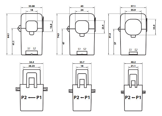
The design and orientation of the measured current direction for bushing transformers are indicated in the following figure.

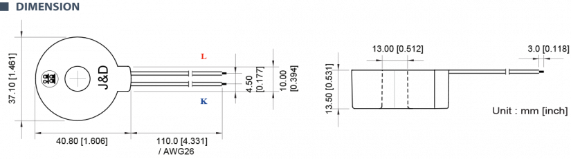
Fig. 2 The correct direction of cable routing through bushing transformers, dimensions are given for type JP5W
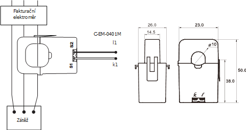
Fig. 3 Correct direction of cable routing through openable transformers, dimensions type JC10F
Divided measuring current transformer
This special type of measuring current transformers can be used for measuring alternating current up to approx. 650 A. Their great advantage is the relatively easy installation and the possibility to install the analyzer even during the operation of the measured device (without the need to disconnect). The split transformer can be easily connected, opened, snapped around the wire and start the measurement.
Basic parameters of openable transformers:
| Model | JC10F/L | JC16F/L | JC24F |
| Type | 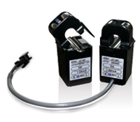 |
|
|
| Hole | 10 mm | 16 mm | 24 mm |
| Current range (recommended) |
0.01~80 A | 0.01~120 A | 0.01~200 A |
| Max. current (permanent) |
120 A | 200 A | 300 A |
| Thread ratio | 3000:1 | 3000:1 | 3000:1 |
| Protection level | 7.5V0-P | 7.5V0-P | 7.5V0-P |
| Phase error | +1.5 ±1° | +1.0 ±1° | +1.0 ±1° |
| Linearity error | -1 ±1% | -1 ±1% | -1 ±1% |
| DCR | 360±25 Ω | 280±20 Ω | 171±15 Ω |
Die-cut current transformer
The JP series transformers represent a very precise series of measuring current transformers, which meets the requirements for energy and power measurement in the 0.1 / 0.2 / 0.5 class. They are designed for different environments: for power sources, measurement in distribution networks and for applications in industry and automation.
They have excellent properties - a small phase and linearity error even at low currents. The JP series also has a better temperature dependence. Meets the requirements of IEC 62053-22, ANSIC12.xx and EN 50470-3 for energy measurement.
Properties
- class 0.2 / 0.5 for measurements for medium and high voltage
- excellent transmission characteristics
- minimum phase error
- high permeability
- certified according to UL, CSA, CE and RoHS
Basic parameters of bushing transformers:
|
Model |
The scope of the primary current |
Phase error |
Threads ratio |
Characteristics |
Connector type |
Dimensions |  |
||||
| I_max [A AC] |
I_peak [A AC] |
L [H] |
Rcu [Ω] |
Rb [Ω] |
Ub [VAC] |
Internal dimension [mm] |
|||||
| JP3W | 6 | - | 0.10 | 1:2500 | 250 | 138 | 10 | 0.024 | Wire type | 7 | |
| JP5W | 120 | - | 0.10 | 1:2500 | 130 | 55 | 5 | 0.24 | Wire type | 13 | |
| JP6W | 200 | - | 0.10 | 1:2500 | 120 | 38 | 5 | 0.4 | Wire type | 19.3 | |
Divided transformers X/100 mA
Current transformers with a secondary current of 100 mA are commonly used in energy management systems and monitoring systems. These transformers include built-in overvoltage protection in case of accidental disconnection, the current transformer does not need to be short-circuited during handling. The split core of the current transformer allows easy installation without the need to disconnect the wires of the measured system. Below are the transformers for installation on the conductor.
Basic parameters of openable transformers X / 100 mA:
| Model |
JS17F - xxx/100mA |
||||||||
| Appearance |
|
||||||||
| Inner diameter |
17 mm |
||||||||
| Nominal current | 50 A, 100 A, 125 A | ||||||||
| Accuracy class | 1 | ||||||||
| Load capacity | 0.01 VA | ||||||||
| Overload |
120 % Inom permanent |
||||||||
| Test voltage |
3 kV for 1 minute |
||||||||
| Level of protection | Bipolar 6.5 Vp (surge protection) | ||||||||
| Installation category |
600 V CATIII, 300 V CATIV |
||||||||
| Output terminals |
2 x M3, with cover |
||||||||
| Schemes |
|
||||||||