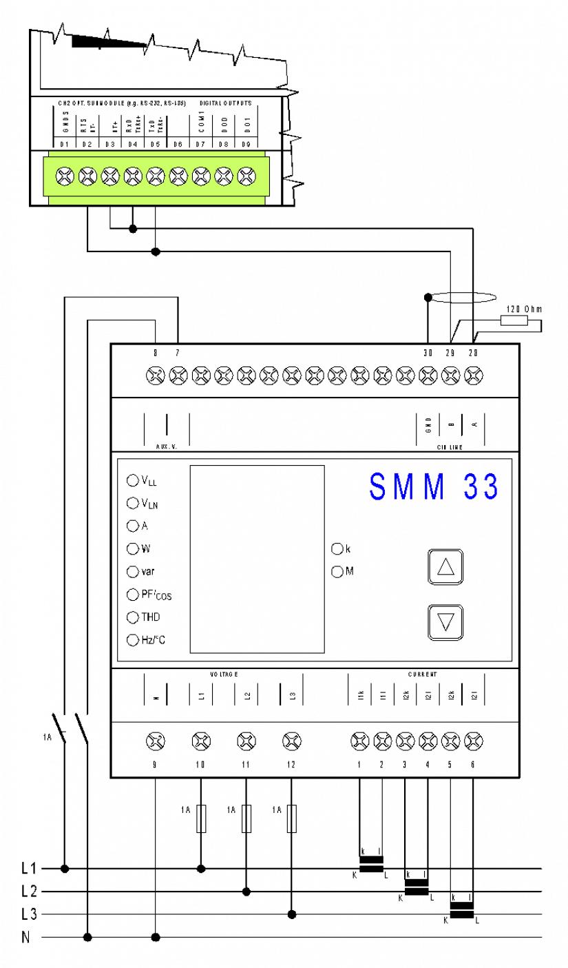
In order to provide a detailed analysis of a 3ph network (measuring and monitoring the line and phase voltages, currents, active and reactive power, the power factor, THD voltages and currents and frequencies in the low-voltage network, etc.), you can use the SMM33 module connected to the communication channel of the Foxtrot basic module. For more information about the Foxtrot communication channels, see the TXV 004 03.
The SMM33 module is equipped with inputs for connecting three voltage signals of nominal value of up to 3 x 230 Vef and three fully isolated current inputs up to 5 Aef.
Supply voltage of the device must be connected to the AUX V terminals via a disconnecting device (a switch - see the example of connection.
It must be located right by the device and it must be easily accessible by the operator. The disconnecting element must be marked as such. A circuit breaker with a nominal value of 1A can be used as a disconnecting device, but its function and status must be clearly marked (by symbols "0" and "I" in accordance with the ČSN EN 61010-1).
The measured voltage should be secured e.g. by a 1 A thermal fuse. The measured voltage can be connected via measuring voltage transformers.
The current signals of measuring current transformers with a nominal value of 5A or 1A must be
brought to the terminal couples I1k, I1l, I2k, I2l, I3k, I3l; however, their orientation must be observed (terminals k, l).
The RS-485 communication line should be connected to terminals A, B and the shielding to the GND terminal. The endpoints of the communication line must be fitted with terminating resistors.
Basic technical parameters of the SMM33 module
|
Supply voltage |
85 ÷ 275 VAC / 45 ÷ 450 Hz, 80 ÷ 350 VDC |
|
Power consumption |
3 VA/3 W |
|
The over-voltage class and the degree of pollution |
III/2 - accoring to ČSN EN 61010-1 |
|
Connection |
galvanically isolated, the polarity is irrelevant |
|
The measured voltage |
( Unom = 400/230 VAC) 4 ÷ 500 VAC/2.3 ÷ 285 VAC (phase-to-phase/phase) |
|
Voltage measurement accuracy |
± 0.5% from the value ± 0>1% from the range ± 1 digit |
|
Input impedance |
660 kΩ ( Li – N ) |
|
Connection |
star pattern |
|
Permanent overload (acc. to IEC 258) |
2 x (i.e. 1,000/570 V) |
|
Peak overload |
4 x for 1 second ( i.e. 2,000/1,140 V) |
|
Frequency |
45 ÷ 65 Hz |
|
Frequency measurement accuracy |
± 0,02 % |
|
Measured current |
0.02 ÷ 7 AAC (Inom = 5 AAC); |
|
Current measurement accuracy |
± 0.5 % from the value ± 0>1 % from the range ± 1 digit |
|
Connection |
galvanically isolated |
|
Permanent overload (IEC 258) |
14 AAC |
|
peak overload |
70 AAC for 1 second |
|
Communication port |
RS-485 galvanically isolated, the Modbus-RTU protocol |
|
Active power ( Pnom = 230*INOM W ) |
the range is limited by the range of measured voltage and current |
|
Measurement accuracy of active power |
±2 % ±1 digit |
|
Reactive power ( Qnom = 230* INOM VA ) |
the range is limited by the range of measured voltage and current |
|
Measurement accuracy of reactive power |
±2 % ±1 digit |
|
The power factor P.F. (accuracy) |
0.00 ÷ 1.00 ±2 %; |
|
Cos φ (accuracy) |
-1.00 ÷ +1.00 L, C ±2 % |
|
THD (accuracy) |
up to 25. order, 0 ÷ 200 %, ( ±2 % ±1 digit, pro U, I > 10 % UNOM ,INOM ) |
|
Operating temperature |
-25 to 60 °C |
|
Maximum wire cross-section for the terminal |
2.5 mm2 |

Fig. 1. An example of connecting the 3ph network analyzer SMM33 to CH2 CP-10x6 (10x8)
