
The access control via a keypad with a proximity card (or similar identifiers) reader is best arranged by utilizing the SAMSUNG-produced SSA-R2000V keypad, which should be connected to the C-WG-0503S module. The sensor is equipped with a numeric proximity keypad and a proximity card reader in two variants: the SSA-R2000V (Samsung Format, 125 kHz) and the SSA-R2001V (MIFARE, 13.56 MHz).
The C-WG-0503S module provides Wiegand communication with the sensor and control of LEDs and the buzzer. Due to the consumption reaching 230mA, the keypad must be powered from an external 12 VDC supply (the 12 VDC output of the C-WG-0503S module cannot be used for this keypad).
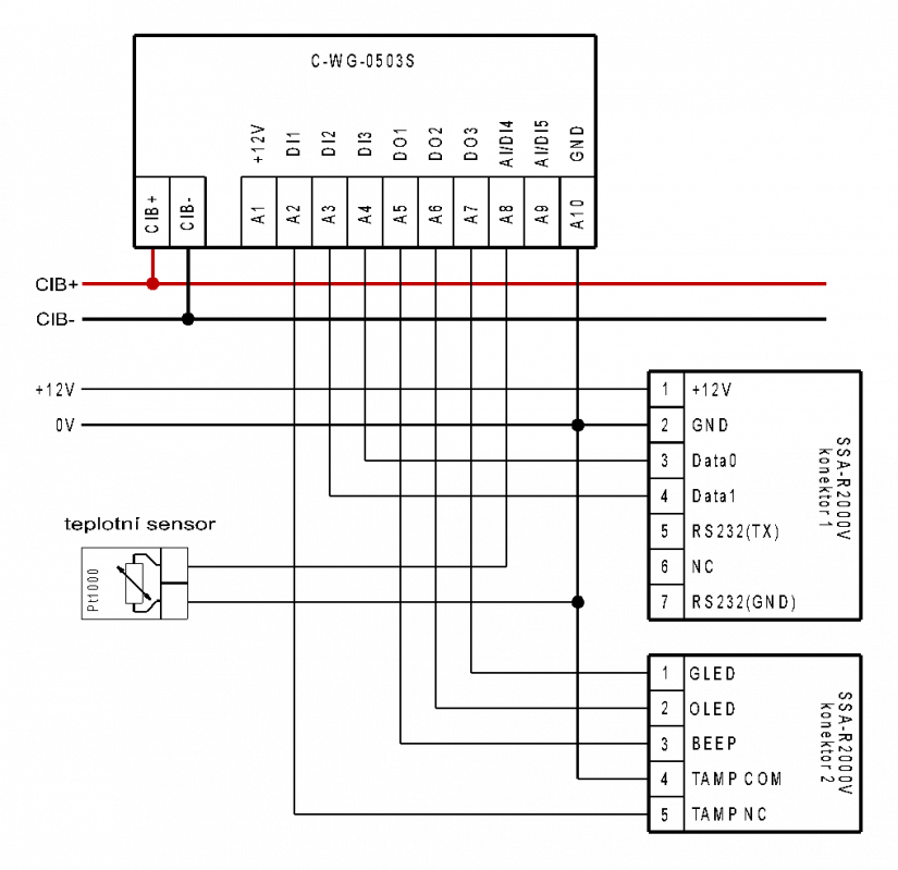
Fig. 1. An example of connecting the SSA-R2000V sensor to the C-WG-0503S module.
Notes:
-
The cable for connecting the sensor can be as dozens of meters long (the Wiegand interface allows the length of up to 150m); the communication and control require a shielded cable with the minimum cross section of 0.35mm2, the power supply only requires an unshielded cable with the minimum cross section of 0.75 mm2.
-
The consumption of the SSA-R2000V sensor from the supply voltage is specified at 230 mA, which does not meet the specifications of the C-WG-0503S module (a maximum consumption from the 12 V output is 60 mA), so the sensor must be powered from an external source.
-
The free inputs AI/DI4 and AI/DI5 can be utilized e.g. for connecting the temperature sensors (measuring the temperature in the room, etc.).
The properties and parameters of the SSA-R2000V sensors
The SSA-R2000V sensor is designed for reading proximity (RFID) identifiers according to the type of technology used - the Samsung 125 kHz Format (SSA-R2000V) or the MIFARE (SSA-R2001V); it is also used for entering the PIN code via the touch keypad. The sensor is equipped with a red, orange and green LED indication and a buzzer.
The sensor is designed for both indoor and outdoor use, it is in a vandal-resistant version, with a contact-free keypad in a compact housing; the interior electronics is embedded for a maximum durability. The module is equipped with a tamper contact against unauthorised manipulation.
The sensor is mounted on the wall with two screws (approx. M3, or 3.5mm wood screws); the layout of the mounting holes is indicated in Fig. 3.; in the middle between the mounting holes in the rear wall there is a fixed connecting cable. The tamper contact is located in the top part, approximately between the mounting holes.
The cable is terminated with free coloured wires moulded into two connectors (see Tab. 2.).
Tab. 1. The basic parameters of the SSA-R2000V and SSA-R2001V sensors
|
Technical parameters |
SSA-R2000V |
SSA-R2001V |
|
Nominal supply voltage |
12 VDC |
|
|
Maximum current consumption |
230 mA 1) |
150 mA 1) |
|
The interface RFID sensor |
26 bits Wiegand |
34 bits Wiegand |
|
The keypad coding |
8 bit code |
8 bit code |
|
Reading distance – ISO card |
max. 10 cm 2) |
max. 10 cm 2) |
|
The RFID frequency range |
125 kHz |
13.56 Mhz |
|
The supported types of identifiers |
PSK 125kHz, Samsung Format |
ISO 14443A Mifare 3) |
|
The type of sensor |
just for reading (read only) |
|
|
Acoustic signal |
buzzer |
|
|
Optical indication |
LED (green, orange, red) |
|
|
The keypad |
contact-free, numeric keys, ESC, ENT |
|
|
Terminating signals |
cable, approx. 100 cm long, a 6.5 mm insulation diameter |
|
|
The cable termination |
2x connector |
|
|
The dimensions of the housing (width x height x depth) |
87 x 109 x 25 mm |
|
|
The range of operating temperatures |
-30 to +50 °C |
|
|
Housing – colour, material |
a silver frame with a black keypad, polycarbonate and aluminium |
|
|
Protection |
IP 68 |
|
-
The current consumption exceeds the 12V output of the C-WG-0503S module, so the sensor must be powered from an external source (e.g. from the 12 V output level of the PS2-60/27 power supply, or from the DR-15-12 supply).
-
The distance is only valid for cards and identifiers supplied by the sensor manufacturer.
-
Only for reading of a unique serial card number.
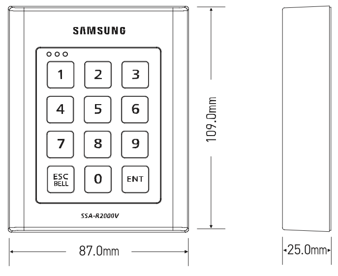
Fig. 2. The dimensions of the SSA-R2000V sensor
Tab. 2. A description of the terminals and signals from the SSA-R2000V sensor
|
Connector PIN |
The colour of the wire |
Function |
Description |
|
|
Connector 1 |
1 |
red |
+12V |
positive pole of the supply voltage |
|
2 |
black |
GND |
the ground of the supply voltage |
|
|
3 |
green |
data0 |
data wire, Data 0 Wiegand interface |
|
|
4 |
White |
data1 |
data wire, Data 1 Wiegand interface |
|
|
5 |
violet |
RS232(TX) |
RS-232 transmitter (not used) |
|
|
6 |
brown |
NC |
not used |
|
|
7 |
orange |
RS232 (GND) |
RS-232 GND |
|
|
|
||||
|
Connector 2 |
1 |
yellow |
GLED |
green LED (it is activated by connecting the signal to GND) |
|
2 |
grey |
OLED |
orange LED (it is activated by connecting the signal to GND) |
|
|
3 |
blue |
BEEP |
buzzer (it is activated by connecting the signal to GND) |
|
|
4 |
pink |
TAMP COM |
the tamper common terminal |
|
|
5 |
light yellow |
TAMP NC |
the tamper NC contact output |
|
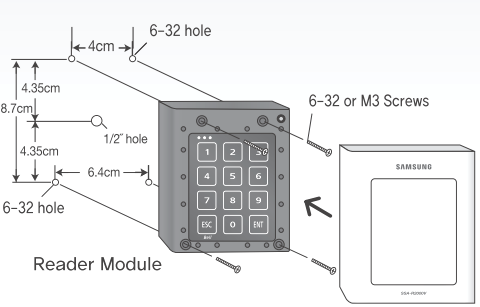
Fig. 3. A drawing of mounting the SSA-R2000V sensor on the wall