
The module is designed to connect readers of proximity RFID identifiers with the Wiegand protocol (e.g. Aktion AXR-100, AXR-110, Samsung SSA-1001, SSA-R2000V, and others) and the intrusion detectors (ESS/FAS sensors including the 12 VDC power supply).
In addition to signals for connecting readers (communication, display) the module also contains 1 dry binary input and 2 universal inputs.
Each of the universal inputs can be used separately either in the function of binary dry input, or as a balanced input (connecting ESS sensors), or as an analogue input for connecting a resistive temperature sensor. The signals for connecting a reader can also be reconfigured for the function of 2 digital inputs and 3 digital outputs. Possible configuration options of the module inputs and outputs are shown in Tab. 1.
The mechanical design of the module is intended for installation under the cover of the IP10B module. The module signals are terminated on a removable connector with loose wires.
The type of coding
The module allows processing codes via the protocol Wiegand 26, Wiegand 34 or Wiegand 42 bits and the transparent transfer 40 bits.
Tab. 1. Configuration options of the C-WG-0503S module (to be set in the module software configuration)
|
Possible configurations |
DI1 |
DI2 |
DI3 |
DO1 |
DO2 |
DO3 |
DI/AI4 |
DI/AI5 |
|
Wiegand, 1x DI, 2x AI/DI, 3x DO |
DI |
Data1 |
Data0 |
DO |
DO |
DO |
AI/DI |
AI/DI |
|
3x DI, 2x AI/DI, 3x DO |
DI |
DI |
DI |
DO |
DO |
DO |
AI/DI |
AI/DI |
Tab. 2. The basic parameters of the inputs and output of the C-WG-0503S module
|
Binary inputs DI1, DI2, DI3 |
|
|
Type |
TTL 5 V |
|
Pull-up resistor |
3.9 kΩ |
|
Galvanic isolation |
No |
|
The Wiegand interface |
26/34/42 bit (3/4/5 bytes) and 40 bits transparent |
|
Binary outputs (DO1, DO2, DO3) |
|
|
Type |
open collector NPN |
|
Switching voltage |
maximum 30 V |
|
Switching current |
maximum 30 mA |
|
Galvanic isolation |
No |
|
Analogue and binary inputs (AI/DI4, AI/DI5) |
|
|
The range (the type of connected sensor): |
Pt1000, W100 = 1,385, -90 to +320 °C Pt1000, W100 = 1,391, -90 to +320 °C Ni1000, W100 = 1,617, -60 to +200 °C Ni1000, W100 = 1,500, -60 to +200 °C NTC 12k, -40 to +125 °C KTY 81-121, -55 to +125 °C OV160k, general resistance 0 ÷ 160 kΩ potential free contact (the input value 0 for >1.5 kΩ/1 for <0.5 kΩ ) single or double balanced input for ESS sensors, resistance 2x 1k1 |
|
Output 12 VDC (+12 V) |
|
|
Output current |
maximum 60 mA (medium value of the output current) |
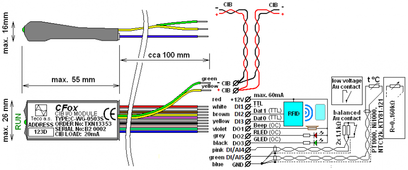
Fig. 1. The signal layout of the C-WG-0503S module, the wire colour coding and the basic connection (the old version before November 2012)
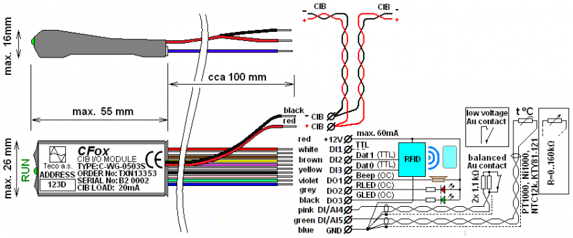
Fig. 2. The signal layout of the C-WG-0503S module, the wire colour coding and the basic connection
(the new version after November 2012)
Notes:
-
The +12 V output has a 12 VDC output voltage available, the maximum medium value of continuous output current is 60mA for powering readers or ESS and FAS sensors (a short-term load can reach approx. 80mA).
-
The module is terminated with a connector with moulded separate colour-coded 100 mm long wires.
-
The CIB bus is terminated separately on two insulated wires.
-
The inputs are opposite the common GND terminal, the outputs switch against the +12 V terminal.
-
The DI1, DI2 and DI3 are only binary inputs, which can be connected either as dry contacts, (3K9 pull-out resistance from the 5 VDC voltage, where the input is switched against GND), or as an TTL compatible input (DI2 and DI3 also allow the connection of a Wiegand device, depending on the configuration).
-
The DI/AI4 and DI/AI5 inputs can be configured to one of these ranges: The sensor Pt1000, Ni1000, NTC 12k, NTC generally up to 160 kΩ, KTY81-121, a potential-free contact, single or double-balanced loop (the input is excited by the 3.3 V voltage via a 2k2 resistor); the input signal is always connected against GND.
-
The DO1, DO2 and DO3 outputs are designed as open collectors NPN, i.e. the output wire is switched against GND directly by the transistor, without resistance in series and other protection elements - the switched load (a LED, a buzzer) must be connected with the other end to the supply voltage (typically 12 VDC in keypads, readers, etc.).
-
The module outputs are insulated wires with the cross-section of 0.14 mm2, the length of approx. 10 cm, terminated with crimped ferrules H0.25/10.
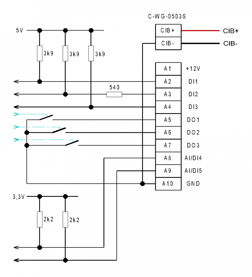
Fig. 3. Internal wiring of the C-WG-0503S module