

Controlling an SSR Using PWM Over ZCC
To control power using a solid-state SSR without interference and with minimal wear, PWM control over zero crossing control can be used. The relay thus switches only at the zero crossing of the mains voltage, thereby minimizing switching losses and electromagnetic interference (EMI).
Control Parameters
- Mains frequency: 50 Hz
- Duration of one period: 20 ms
- Number of PWM steps: 20 (each step = 5% of power)
- PWM cycle: 20 mains periods = 400 ms
- PWM frequency: 2.5 Hz
Calculation
We want to control the power in 5% increments, i.e., 20 different levels (0–100%). Each level corresponds to a whole number of power grid periods. This ensures that the SSR always switches on for whole power grid periods.
PWM cycle length:
= 20 × (1 / 50 Hz)
= 20 × 20 ms
= 400 ms
PWM frequency:
= 1 / 400 ms
= 2.5 Hz
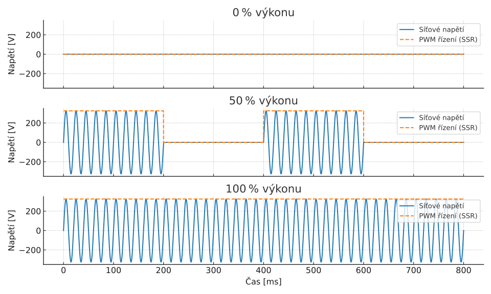
Illustrative graph
The graph shows three examples of power control using full grid periods (two periods of the PWM signal are shown):
- 0% power – the SSR is off for the entire cycle
- 50% power – the SSR is on for the first 10 periods, then off for the next 10 periods
- 100% power – the SSR is on the entire time
Notes
- The relay must be capable of detecting zero-crossing and switching at zero crossing.
- Suitable for resistive loads, such as heaters, incandescent bulbs, or electric space heaters.