
The central module contains a central unit, which is the main part of the TECOMAT TC800 PLC assembly. Its main task is to execute a user program, control PLC inputs and outputs and communicate with the PLC environment.
The central module also contains two independent Ethernet interfaces, one micro-USB device interface for connecting the master system and one USB host interface for connecting an external memory (USB Flash drive).
The integrated 4 x 10 character display and 6 buttons are used to set up and diagnose the system.
The central module also contains a slot for mounting an additional micro SD memory card (not available in variants with installed WLAN1 interface).
Optionally, the central module can be equipped with two submodules, eg with serial channels or other buses.
The central unit in the CP-8001 module is described in the following article.
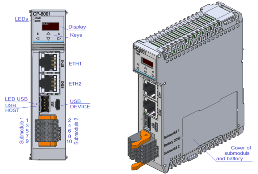
Fig. 1. TC800 central module
TCL3 peripheral bus
It is a basic bus that is used to connect peripheral modules of the TC800 family. The bus is inserted into the U-rail, on which the individual modules of the assembly are mounted. The internal line (IOP 1) can serve up to 64 modules.
TCL2 peripheral bus
This is the basic bus that is used to connect peripheral modules of the FOXTROT family. Up to two TCL2 bus lines can be added to the TC800 system using SE 0140 interchangeable submodules.
The individual lines of the TCL2 bus are completely independent of each other, so that the addressing of peripheral modules on the line takes place according to the rules, regardless of the occupancy of other lines. The only limitation that still applies is the total maximum number of 10 serial channels for the entire system, which is determined by the capacity of the central unit.
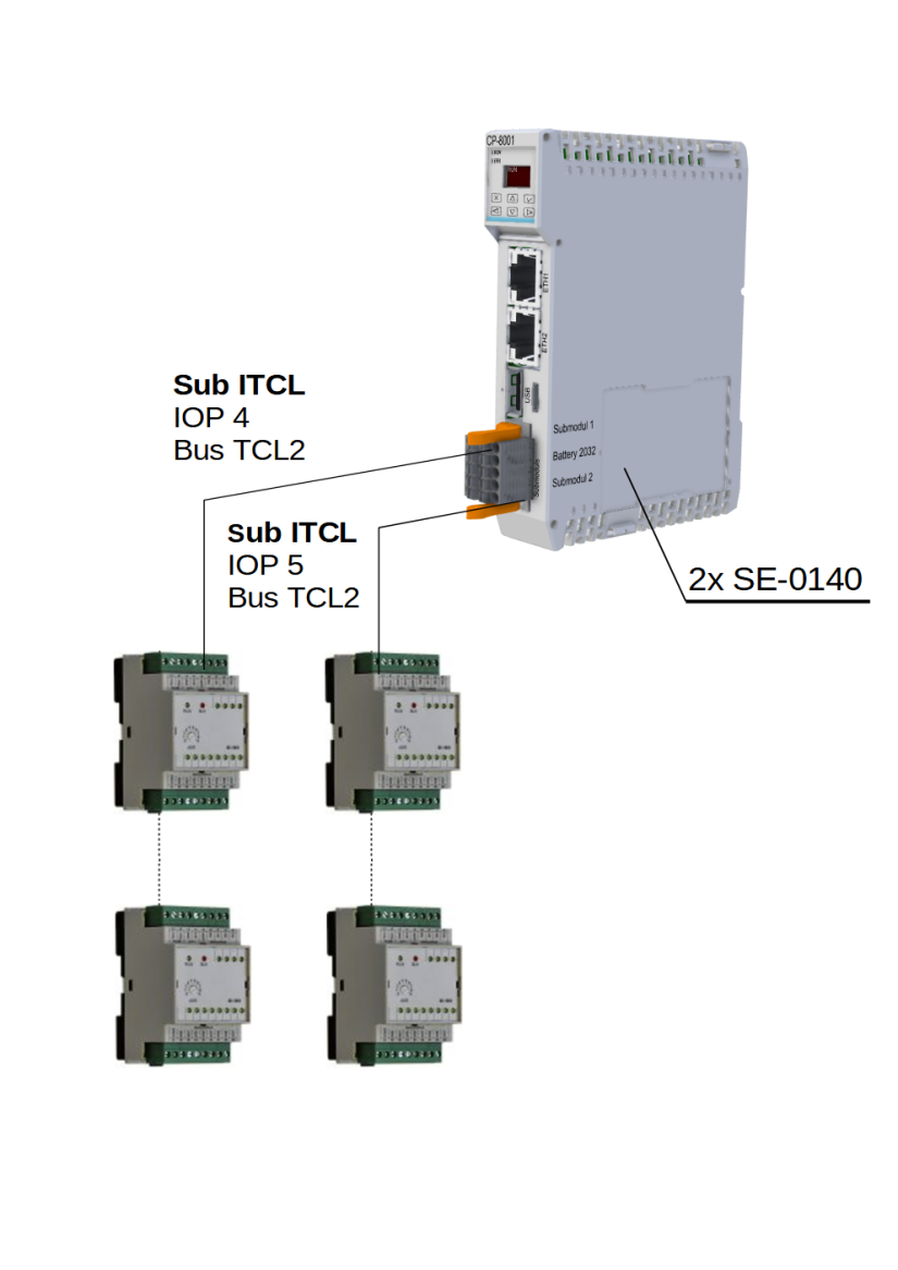
Fig.2 Example of an assembly with two TCL2 buses
Notes:
- This bus uses metal cables to connect, corresponds to the RS-485 interface and must be terminated at both ends. Submodules SE-0140 contain the end of the bus and must always be at its end. At the other end, the bus must be connected to the last module together with the KB 0290 terminator (one piece is part of the delivery of the SE-0140 submodule).
- Both submodules installed in the central PLC module have a common signal ground COM1, which is galvanically separated from the internal circuits of the PLC.
- The submodules are reported on the internal ITCL bus as IOP 4 (position 1) and IOP 5 (position 2). These labels are used to identify a specific bus in case of error messages
CIB installation bus
It is a two-wire installation bus, which is used to connect CFox family modules. Both data communication and power supply of modules are realized by two wires.
Up to 7 CF-2141 external CIB masters can be connected to the TC800 system via the ETCL bus via the ETH1 or ETH2 Ethernet interface. CIB master CF-2141 contains 1 CIB bus line, including power supply with the ability to take modules on the line up to 1 A.
A separate documentation Peripheral modules on the CIB bus TXV 004 13.01 is dedicated to the CIB bus and CFox family modules.
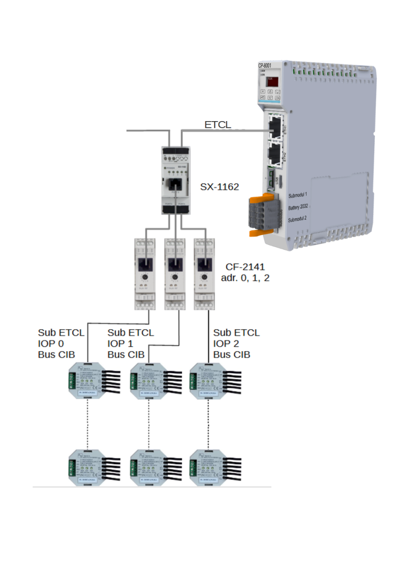
Fig.3 Example of an assembly with three CIB buses
External ETCL system bus
The ETCL bus is implemented on the Ethernet interface and is mainly used to connect masters of other buses.
It is currently used to connect CF 2141 CIB masters. ETH1 or ETH2 interfaces can be used to connect the ETCL bus, but only one of them at a time.If more than one module is connected, the SX-1162 module (five-port Ethernet switch) can be used for interconnection. It is recommended that all Ethernet switch modules used in the ETCL bus be of the same type (do not combine SX-1162 modules with other Ethernet switch types). A unique ETCL address must be set on each CF-2141 module.