
The C-1W-4000M module is connected to the PLC via the CIB interface.
When testing the correct connection, it is sufficient if the module is connected only via USB, as it is also powered by it.
-
Use the 1-WIRE GWY TOOL tool (download HERE) to check the correct function of the sensors and assign them to the individual channels. One 1W line is for a maximum of 20 channels, ie. 20 sensors.
-
Connect the G-1W-4000M to a computer via USB
-
Run the 1-WIRE GWY TOOL
-
Click USB and Connected
-
For each line: Add new -> Find all, finds all connected sensors.
-
After clicking Save to select the channel for the sensor, you can leave the original number. These channel numbers correspond to the CHAN variable (below).
-
If a sensor does not appear, it is necessary to check whether it is connected correctly or whether more than 20 sensors are connected to the given 1W line.
-
If a problem occurs, the channel or the entire line may turn red and an error message will appear describing the problem.
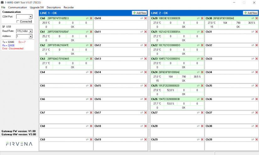
The error message Err = 7 - Disconnected is displayed on the left because the picture was taken when the USB cable was disconnected.
Four sensors are connected in LINE1, seven sensors in LINE2. For example, the script below can be used to load their values into Mosaic.
PLC connection to PC
-
Connect the supply voltage and connect to the PC using an ethernet cable.
-
Press MODE and ↓ to display the IP address of the module.
-
At the PC command prompt, use the ping command to verify the connection to the PLC.
-
If there is no response, it is necessary to adjust the IP address of the PC (adapter) so that it differs from the PLC only in the last part, eg PLC: 192.168.134.176, PC: 192.168.134.10
In Mosaic
-
File → New Project Group → click, enter group and project name, instance name, select I/O Configurator for Foxtrot/Foxtrot 2
-
When opened, an editor will appear, on the left the file system, on the right the I/O configurator.
-
After clicking on the Project Manager icon (next to the File tab), the connection options will be displayed. Select Ethernet
-
Enter the IP address of the PLC in the local network selection. The other fields can be left in their original state and click to connect.
-
Once connected, the text Connected and dynamic timeout will appear on the top bar
-
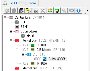
In the I/O configurator, click on the Currently connected HW configuration icon and load it. (PLC restart may be required - red power icon)
-
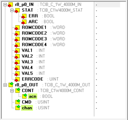
After clicking on the C-1W-4000M tab in the I/O configurator, the input and output values appear.
Variables
-
VALUE:int – sensor output values on the CHAN channel
-
CHAN:usint – the channel (sensor) number from which the output values will be read the next time the ACN is changed.
-
ACN:bool – when changing, a command is sent for the sensor on the CHAN channel to send data.
Process
-
CHAN is set according to which sensor we are interested in
-
ACN will change – a measurement request is sent
-
The sensor output values are stored in VALUE
You can build a simple script that will jump between sensors at certain intervals and display their data.
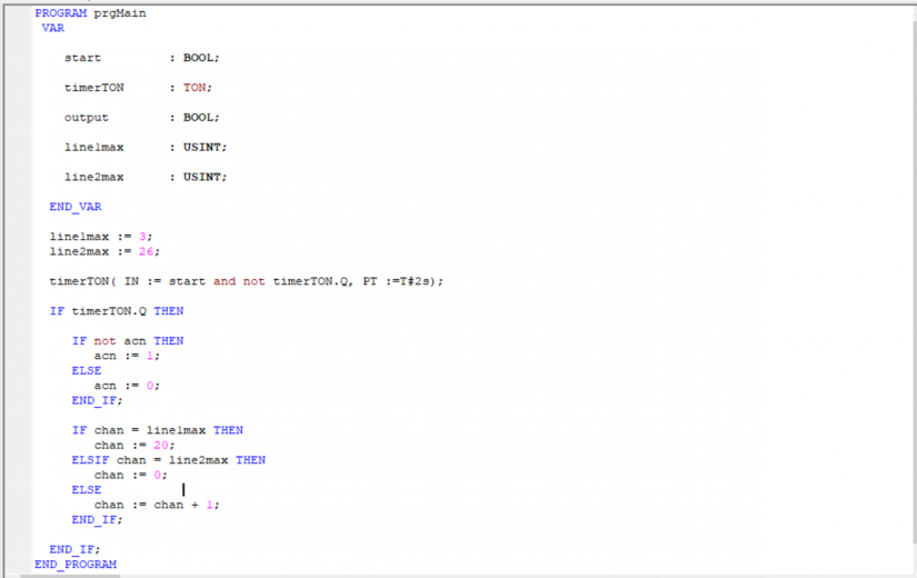
After 2 second intervals, the script cycles between the individual channels and reads the output values of the sensors on the given channel. The cycle takes place: 0 → line1max → 20 → line2max → 0 →…
The line1max variable specifies the highest channel index used on LINE1, as well as line2max on LINE2. Channels for LINE1 generally have indices from 0-19, on LINE2 20-39. It is assumed that the sensors are on consecutive channels, ie for example a total of 4 sensors on LINE1 would be on channels with indices 0,1,2,3, line1max would have a value of 3.
Launch
-
Compile – icon on the top bar (F9)
-
Run – next to the Translate icon (Ctrl + F9), confirm sending the code, cold start
-
In the bottom bar in the Data tab, set main.start to the value 1-start timer
-
The output values start updating every 2 seconds
More information about the peripheral module is available in the Mosaic help.