
1-WIRE – Introduction
1-Wire is a bus designed by Dallas Semiconductor Corp. for device communication at low data rate, signaling and power supply. 1-Wire is similar to the I²C, bus, only with lower data throughput and longer range. It is usually used to communicate with small, inexpensive devices such as thermometers and various other devices. The network from a 1-Wire device with a connected master device is called MicroLAN..
A 1-wire device can be one of many components on a circuit board, or just a single element in a device, such as a temperature sensor, or it can be connected to a device that is being monitored. It is possible to connect a 1-Wire device via a modular connector, or a CAT-5 cable to a device in a socket, to a small PCB board, or to another monitored element. In this case, the RJ11 connector (6P2C or 6P4C) is popular.
The system of sensors and actuators can be connected together using 1-Wire components. Each component contains all the logic required to operate on the 1-Wire bus. Examples are temperature recorders, timers, voltage and current sensors, battery and memory monitoring. These can be connected to a PC using a device to change the bus type. USB, RS-232, serial and parallel interface ports are popular solutions for connecting MicroLan to a host computer. 1-Wire devices can also be connected directly to microprocessors from various vendors.
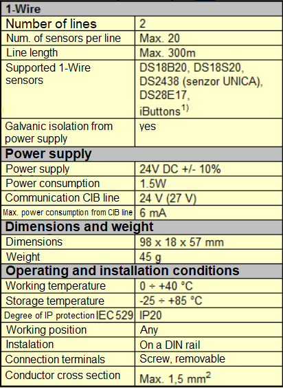
Peripheral module C-1W-4000M
Module for connection of up to 40 sensors via 1-Wire communication buses (low-speed data bus designed by DALLAS). There are two 1-Wire buses on the module, each allowing the connection of up to 20 sensors.
The signaling green RUN LED is accessible on the module. The connection of the module to the CIB bus is signaled by the steady light of the RUN LED, the operation of the module from the CIB is signaled by the regular flashing of the RUN LED.
Table of basic parameters
CONNECTION AND ADJUSTMENT OF 1-WIRE SENSORS USING FOXTROT 2 AND C-1W-4000M
-
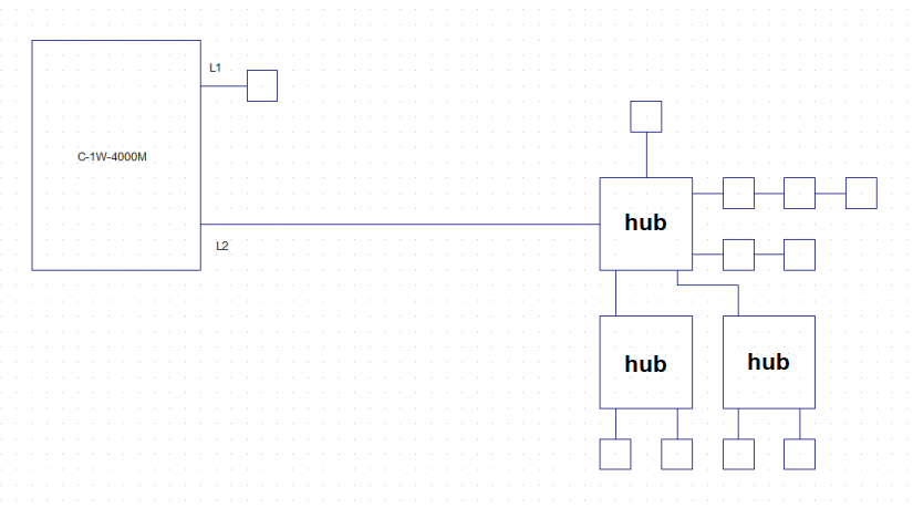
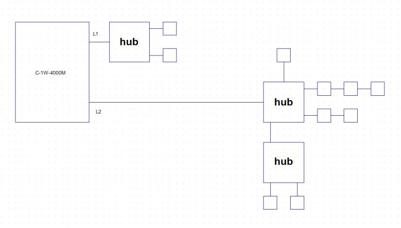
Connect sensors and wires. Examples of connections are shown in the following diagrams.
(the square indicates the sensor)


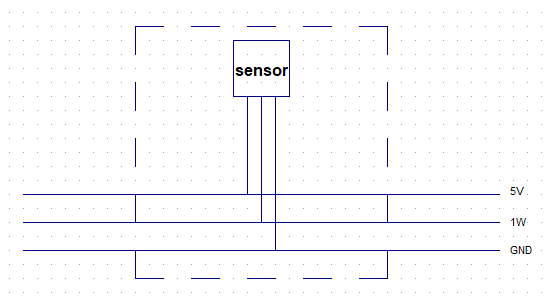
Sensor connection - zoomed in
All sensors can be connected to one LINE, if there are a maximum of 20. They can also be connected in various combinations shown in the diagrams.
The hub has the same effect as if the wires were simply branched. When connecting, make sure that the 1W input, power supply and GND are connected to the connectors marked INPUT on the back of the PCB.
The circular topology cannot be used with a 1-Wire network.
SW configuration and operation is described in the next article.