
The CP-1016 is the basic module of the Foxtrot control system. The standard version is in a 9M housing on a DIN rail (for the housing dimensions, see Chapter 13.2.1 9M housing on a DIN rail), and it is fitted with six removable terminal blocks.
The I/O layout:
Power supply 24 VDC, power consumption max. 10 W (information on power supply see Chapter 2.2)
AI0 ÷ AI5 6 analogue inputs, without galvanic isolation, with an optional function of a binary input:
-
ranges: Ni1000, Pt1000, OV1000, binary input potential free contact
AI6 ÷ AI12 7 analogue inputs, without galvanic isolation with an optional function of a binary input:
-
ranges: 0÷20 mA, 4÷20 mA, Ni1000, Pt1000, OV1000, binary input potential free contact
DI13 pulse input (for a flow-meter, etc.), potential free contact
DI14 binary input 230 VAC (e.g. ripple control), with galvanic isolation
AO0-1 2 analogue outputs, without galvanic isolation, range 0 ÷ 10 V
DO0, DO1 2 semiconductor outputs, galvanically isolated from other circuits, 1 A, 230 V, SSR, outputs can be set to PWM mode
DO2 ÷ DO11 10 relay outputs, galvanically isolated from other circuits, 3A on the output,
ETH Ethernet 10/100 Mbit (a standard RJ-45 connector), with galvanic isolation from other circuits, see Chapter 2.4.1
CH1 Serial channel, with fixed RS-232 interface, without galvanic isolation, see Chap. 2.3.1
CH2 Serial channel, with a possibility of fitting with standard submodules, see Chapter 2.3.3
|
The analogue inputs |
AI0 ÷ AI5 |
AI6 ÷ AI12 |
|
Temperature sensor Pt1000, W100=1.385 or 1.391 |
-90 °C ÷ +270 °C |
-90 °C ÷ +270 °C |
|
Temperature sensor Ni1000, W100=1.500 or 1.617 |
-60 °C ÷ +155 °C |
-60 °C ÷ +155 °C |
|
Temperature sensor KTY81-121 |
-55 °C ÷ +125 °C |
-55 °C ÷ +125 °C |
|
Resistance ranges |
0 ÷ 1 kΩ (OV1000) |
0 ÷ 1 kΩ (OV1000) |
|
Current ranges |
- - |
0 ÷ 20 mA 4 ÷ 20 mA |
|
Input resistance for current ranges |
- |
100 Ω |
|
Internal voltage for power supply of resistance sensors |
8.34 V |
|
|
Conversion time of channel |
typically 50 μs |
|
|
Recovery time of each channel value |
typically 650 μs |
|
Notes:
-
The current ranges require inserting a jumper for the relevant input. The jumpers are located under the cap with the numbers and names of terminals (above the C connector).
|
Binary inputs |
DI0 ÷ DI12 |
DI13 |
DI14 |
|
Input voltage for log. 0 |
min. +2.3 VDC max. +12 VDC |
max. 120 VAC |
|
|
Input voltage for log. 1 |
max. +1VDC |
min. 200 VAC max. 250 VAC |
|
|
Input current in log. 1 |
typically 1.7 mA |
typically 5 mA |
|
|
A The minimum width of the captured pulse |
20 ms |
50 μs |
- |
|
Max. frequency |
- |
5 kHz |
- |
Notes:
-
The DI0 ÷ DI3 and DI13 inputs allow to switch on the function of capturing short pulses. This function checks the input signal level to ensure that no pulse shorter than the cycle of the programme will be lost (e.g. for connecting pulse outputs of flowmeters, etc.).
-
The DI13 input can be set in the counter mode, e.g. for pulse outputs of flowmeters, and such like.
The analogue output AO0, AO1
|
Output range |
0 ÷ 10 V |
|
Maximum output value |
105 % of the output range upper limit |
|
Maximum output current |
10 mA |
|
Maximum load capacity |
50 nF |
The relay outputs of the CP-1016 module
| The DO0, DO1, SSR (solid state relay) outputs with a common terminal, continuous output current 1 A, inrush 1 A, max.continuous current in common terminal COM1 is 2 A. The outputs are fitted with an SSR relay switching at zero. They can be used as PWM outputs to control e.g. revolutions of small asynchronous motors (fans, circulation pumps). | 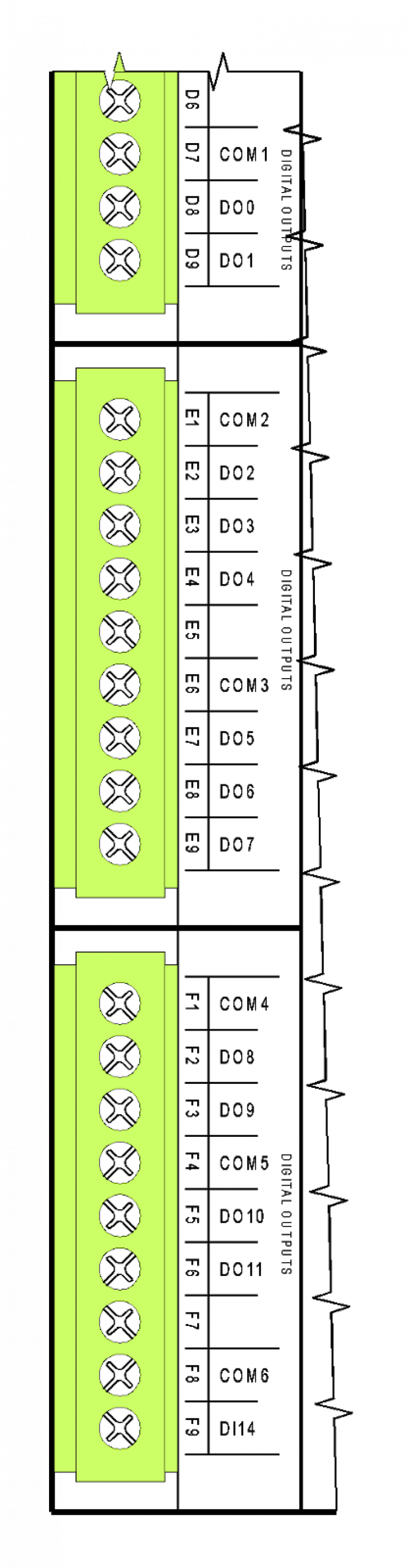 |
| Isolation voltage among groups of outputs and from other circuits is 3750 VAC, i.e. safe isolation of circuits. | |
| The DO2 ÷ DO4, outputs with a common terminal, continuous current in the 3 A output, inrush 5 A, max.continuous current in common terminal COM2 is 10A, more detailed information on relay contacts. | |
| Isolation voltage among groups of outputs and from other circuits is 3750 VAC, i.e. safe isolation of circuits. | |
| The DO5 ÷ DO7, outputs with a common terminal, continuous output current is 3 A, inrush 5 A, max.continuous current in common terminal COM3 is 10 A, more detailed information on relay contacts. | |
| Isolation voltage among groups of outputs and from other circuits is 3750 VAC, i.e. safe isolation of circuits. | |
| The DO8 ÷ DO9, outputs with a common terminal, continuous output current is 3 A, inrush 5 A, max.continuous current in common terminal COM4 is 6 A, more detailed information on relay contacts. | |
| There is only 1750 VAC working isolation among these groups. | |
| The DO10 ÷ DO11, outputs with a common terminal, continuous output current is 3 A, inrush 5 A, max.continuous current in common terminal COM5 is 6 A, more detailed information on relay contacts. | |
| Isolation voltage among groups of outputs and from other circuits is 3750 VAC, i.e. safe isolation of circuits. | |
| The DI14, 230VAC input, suitable mainly for connecting ripple control signal, for an example of connection see Chapter 12.4.1 Scanning ripple signal, basic module CP-1006. |
For principles of protection and usage for capacitive and inductive loads, see Chapter 13.7.1 Protection of output elements (relays,...).
The terminal block of the basic module is made up of connectors with a cage terminal with the spacing of 5.08 mm. Detailed parameters of the terminals are specified in Chapter 13.3.1 Connectors with screw terminals, spacing 5.08 mm, modules on a DIN rail
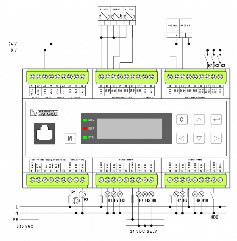
Fig. 1 An example of standard connection of the basic module CP-1016
Wiring notes:
-
Groups of relay outputs (DO0 ÷ DO1, DO2 ÷ DO4, DO5 ÷ DO7 ) can switch circuits powered from different sources. The groups are separated by isolation corresponding to a safe circuit isolation.
-
The output groups DO8 ÷ DO9 and DO10 ÷ DO11 are mutually separated only by working isolation. The isolation from other circuits is in accordance with the principles of safe isolation of circuits.
-
Optional functions of AI inputs are set from the programming environment, only the current ranges 20 mA (AI 6 to AI12) have to be set by jumpers located under the top right cap (above the terminal block).
-
The TCL2 bus is firmly terminated in the basic module and it must always be at the end of the bus line (see Chapter 3.3 TCL2 bus – principles of design and installation).
-
The module power supply, the TCL2 interface, the CIB and the CH1 have a common signal ground, a GND terminal (A3 terminal). This terminal is galvanically connected with the common terminal AI/AO (terminal B1 a C1).
-
The analogue inputs are configured as inputs with a common negative terminal GND.
-
The A3 and B1 terminals and C1 (GND) in the application should not be connected. The C1 terminal is used in the case of 0 to 20 mA or 4 to 20 mA current loops supplied from another 24 VDC source galvanically isolated from the source powering the basic module itself.
-
The DI0 to DI12 inputs are designed to connect a potential free contact. The common signal of binary inputs should be connected to the GND (A3) terminal.
-
The DI13 input is designed to process the pulse outputs, e.g. from a flow-meter or a water meter; the input is intended for potential free contact (minimum captured pulse width is 50 μs.
-
DI14 is a 230VAC input, it is also rated for 400 VAC phase-to-phase voltage (e.g. for processing ripple control signal). The input isolation from other circuits is in accordance with the principles of safe isolation of circuits.