
For fast and accurate measurement of 3f network (measurement of phase voltages, currents, active and reactive powers, power factors, THD voltages and currents and frequencies in the LV network, etc.), in the range of rated currents from 15 A to 150 A (according to the meter configuration ) we can use the electricity meter PA 144 connected to the communication channel of the basic module Foxtrot. More detailed information about communication channels can be found in the TXV 004 03 documentation.
The supply voltage of the electricity meter must be connected to terminals X1 and X2 via a disconnecting element (circuit breaker - see the following connection example). It is suitable to use a circuit breaker with a nominal value of 1 A as a disconnecting element.
The measured voltages should be protected, for example, by a 1 A fuse. The measured voltages can be connected via measuring voltage transformers.
Connect the current signals of the measuring transformers (selection of the transformer according to the current range and the method of installation) to the pairs of terminals l1, k1, l2, k2, l3, k3, l4, k4, their correct orientation must be observed is described in detail in the notes to the following wiring example).
The RS-485 communication line is connected to terminals A, B and the shield to terminal GND. The end points of the communication line must be fitted with terminating resistors.
It is possible to order the PA 144 electricity meter with other ranges of maximum measured currents (from 5 A to 600 A), with two variants of current transformers (bushing and opening) and also with Ethernet communication interface (Modbus TCP protocol). At the same time, instead of the PA 144 electricity meter, the SMC 144 network analyzer can be supplied, which has exactly the same electrical connection, including transformer variants, but differs with added other network analysis functions, including quality analysis according to EN 50 160, eg outages, micro outages, power drops etc.
Electricity variants according to the current range and type of measuring transformers are listed in the following tables (always all 4 current inputs of the electricity meter have identical transformers):
Design with bushing transformers:
| Max. measured current | 15 A | 35 A | 75 A | 150 A |
| Ord. number | PA 144 U P015 N N N | PA 144 U P035 N N N | PA 144 U P075 N N N | PA 144 U P150 N N N |
| Type of measuring transformer | JP3W |
JP5W |
||
| Inner diameter of the hole for the measured conductor | 7 mm |
13 mm |
||
| External dimensions transf. | 24 x 27 x 11 mm |
37 x 41 x 14 mm |
||
Design with openable transformers:
| Max. measured current | 75 A | 150 A |
| Ord. number | PA 144 U S075 N N N | PA 144 U S150 N N N |
| Type of measuring transformer | JC10F | JC16F |
| Inner diameter of the hole for the measured conductor | 10 | 16 |
| External dimensions of the transformer | 23 x 50 x 26 mm | 30 x 55 x 31 mm |

Fig. 1 Example of 3f network measurement connection with PA 144 device connected to CH2 CP-10x6 (10x8)
Notes:
- Terminal A of the RS-485 communication line is connected to terminal TxRx + of the communication interface of the Foxtrot system (analogously terminal B to terminal TxRx-). We will end the communication interface at both ends correctly - see the example.
- It is suitable to connect voltage measuring inputs via fuses of approx. 1 A.
- We connect current transformers with the correct polarity. White wire to terminal k, black wire to terminal l of the respective input.
- Pass the measured conductor through the transformer opening so that on the encapsulated side (yellow side) the output leads towards the appliances, on the black side (in the following figure "source side") the conductor is connected to the installation power supply (applies to standard connection of installation consumption measurement).
- Feed-through transformers are supplied with insulated stranded conductors with a length of approx. 110 mm.
The design and orientation of the measured current direction for bushing transformers are indicated in the following figure, the dimensions are given for type JP5W.
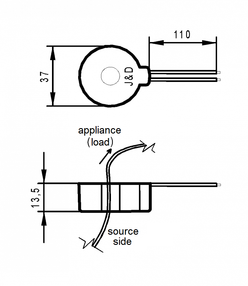
Fig. 2 Correct direction of cable routing through the bushing transformers
Electrometer PA 144 - basic properties.
PA 144 measures energy in four quadrants (kWh and KVArh) and other current values of electrical quantities (frequency, voltage and currents including THD and harmonics, power and power factor, etc.). It transmits the data obtained in this way over the communication line. If necessary, it can be extended to a full-fledged analyzer and data-logger SMC 144.
- four independent voltage inputs (terminals L1 to L4) measured against the zero input (terminal N)
- four bushing (variant P) or split (variant S) current sensors with nominal current selectable in the range of 5 to 600 A
- power supply: 75 - 510 VAC (optionally also voltage 24-48 VAC or 20-75 VDC), terminals X1, X2
- 128 samples per period, voltage and current inputs are read continuously without delays, gaps and outages, the basic measurement interval is 200 ms
- calculation of harmonic voltages and currents up to the order of 63
- evaluation of all commonly measured single- and three-phase quantities such as powers (active, reactive, apparent, deformation and fundamental active and reactive power), power factor, harmonics and THD currents and voltages
Basic technical parameters of the PA 144 electricity meter
| power voltage | 85 ÷ 275 VAC / 45 ÷ 450 Hz, 80 ÷ 350 VDC |
| power consumption | 7 VA / 3 W |
| overvoltage class and degree of pollution | III / 2 - according to ČSN EN 61010-1 |
| connection | galvanically isolated, regardless of polarity |
| measured voltage | ( Unom = 400/230 VAC ) 11 ÷ 520 VAC / 6 ÷ 300 VAC ( combined / phase ) |
| voltage measurement accuracy | ±0,05 % of value ± 0,02% |
| input impedance | 2,7 MΩ ( Li – N ) |
| connection | star |
| permanent overload (according to IEC 258) | 1300V (UL-N) |
| peak overload | 1950V (UL-N) for 1s |
| frequency | 50/60 Hz (42 ÷ 57 / 51 ÷ 70 Hz) |
| frequency measurement accuracy | ±20 mHz |
| measured current | 0,0025 ÷ 1,2× Inom A (according to configuration, Inom = Pxxx) |
| current measurement accuracy | ±0,05 % of value± 0,02 % of range |
| connection | indirect, via external transformers |
| permanent overload (IEC 258) | 2 × Inom |
| peak overload | 20 × Inom (pro Inom < 35 A), 10xInom (pro Inom 35 ÷ 100A) |
| communication port | RS-485 galvanically isolated, Modbus-RTU protocol (optional Ethernet Modbus-TCP) |
| active power ( Pnom = 230*INOM W ) | range limited by the range of measured voltage and current |
| accuracy of active power measurement | ±0,5 % ±0,005 % Pnom |
| reactive power ( Qnom = 230* INOM VA ) | range limited by the range of measured voltage and current |
| accuracy of reactive power measurement | ±0,5 % ±0,005 % Pnom |
| energy measurement | 4 (6) quadrants, the range is limited by the range of measured voltage and current |
| accuracy of active energy measurement | Class 1 according to EN 62053-21 |
| accuracy of reactive energy measurement | Class 2 according toEN 62053-23 |
| power factor P.F. (accuracy) | ±0,005 |
| cos φ ( accuracy) | ±0,005 |
| THD ( accuracy) | to the 50th order, 0 ÷ 20 %, ±0,5 |
| operating temperature | -25 ÷ 60 °C |
| Maximum conductor cross section to the terminal | 2,5 mm2 |