
The TECOMAT FOXTROT 2 programmable controllers represent a new generation of control systems based on the previous TECOMAT FOXTROT series. These are small compact machines with the possibility of modular expansion. They combine the benefits of compact size and modular systems in size and expandability.
The individual modules of the system are enclosed in plastic protective cases, which are mounted on the U rail ČSN EN 50022. Thanks to this, they can be handled without the risk of damage to sensitive CMOS components. The whole system is designed according to ČSN EN 61131 standard.
System basis
The basis of the FOXTROT 2 system is a basic module containing a central unit, various combinations of inputs and outputs, and in most variants a built-in display of 4 x 20 characters and 7 buttons.
Communication interface
The basic modules of the TECOMAT FOXTROT 2 series are equipped with two independent 10/100 Mb Ethernet interfaces. Optionally, they may include a WLAN interface for WiFi communication and an LTE interface for communication over a GSM network.
For serial communication, up to 2 submodules containing 1 or 2 serial channels with RS-232 or RS-485 interface can be optionally fitted to the base module. So the base module can be equipped with a maximum of four serial channels. Additional 6 serial channels can be added using SC-11xx modules on TCL2. RS-232 / RS-485 interfaces, CAN interface or wireless network are available here.
Central unit
The central unit is the main part of the basic PLC FOXTROT 2 module. Its main task is to execute the user program, control the inputs and outputs of the PLC and communicate with the PLC surroundings.
Each central unit in the TECOMAT PLC systems has an assigned letter that specifies a series. Each row of central units has its specific features important to the user program compiler, such as the range of the instruction set and the way it is encoded, mapping variables, and the amount of memory space, and etc.
The central units in FOXTROT 2 systems are Series I. These units have the following features:
-
1 MB of memory for user programs
-
128 MB internal file system, among other things for project archiving
-
Optional 128/256 KB DataBox Archiving Memory (Variant by Option)
-
320 KB of memory for variables, of which 48 KB for RETAIN variables
-
RTC real time circuit
-
integrated Web server
-
integrated Datalogger
-
possibility to change the user program online (without stopping the procedure)
Tab. 1.1 Basic parameters of the central unit
| Module type | CP-2xxx.x1xxxx
ARMv7 792 MHz, 1 core |
| Central unit series | I |
| User program memory | 1 MB |
| Length of instruction | 4 bytes |
| Program source code backup in PLC | yes, optional in Mosaic |
| On-line program change in PLC | yes, including changing I / O configuration |
| Memory for user program variables | 320 KB |
| of which for RETAIN variables | 48 KB |
| IEC Timers / Counters | supported |
| Number of IEC timers / counters | limited by memory size only |
| Cycle time per 1k logic instructions | 0,036 ms |
| Cycle time per 1k integer operation | 0,043 ms |
| Cycle time for 1k floating point operations | 0,044 ms |
| Additional DataBox Data Memory (Internal) | 128/256 KB (by variant) |
| Memory for I / O data | 64 KB / 64 KB |
| File system | |
| PLC internal disk | 128 MB, journaling FS |
| RAM disk PLC | 16 MB |
| USB Flash disk | supported |
| Micro SD card | supported (except WLAN1 variants) |
| Development environment | Mosaic v2018.2 or higher |
| Programming languages | ST, LD, FBD, CFC, SFC (since 2Q 2019) |
| Real Time Circuit (RTC) | yes |
| RTC Backup | typ. 500 hours |
| Integrated Web server | yes |
| Integrated Datalogger | yes |
| Access to PLC variables via web API | yes |
Construction of a extensive system
The basic PLC module can be expanded if necessary by connecting peripheral modules. Expansion peripheral modules are connected to the central unit via serial buses. As a result, the individual components of the TECOMAT FOXTROT system can be distributed in a decentralized manner, so that the individual modules are located directly at the controlled technologies, thus saving power cabling.
Connection with superior system
The entire system can communicate with superior systems (PCs, operator panels, etc.) that can be used for both monitoring and controlling the controlled process. The personal computer also serves to create and debug a PLC user program.
Other system features
When the PLC power supply is turned off, the real time and calendar (RTC) data is backed up. The backup is provided by a supercap, which lasts for about 500 hours.
The basic module CP-2xxx can also be powered via the ETH1 interface using a so-called power injector. The 24 V supply voltage is routed through an Ethernet cable with two pairs of wires not used for signals (Tab. 1.2). Power is always routed through each pole by a pair of conductors. The polarity of the power does not matter, it is on the PLC side treated with an input rectifier. As a result, both direct and crossover cables can be used.
Tab. 1.2 ETH1 Interface Connections (Front View of PLC Connector)
|
|
Pin | Signal | Wire colour |
| 8 | PWRB | brown | |
| 7 | PWRB | white / brown | |
| 6 | RD– or TD– | green or orange | |
| 5 | PWRA | white / blue | |
| 4 | PWRA | blue | |
| 3 | RD+ or TD+ | white / green or white / orange | |
| 2 | TD– or RD– | orange or green | |
| 1 | TD+ or RD+ | white / orange or white / green |

PWRA, PWRB one and the other pole of the PLC 24 VDC (polarity doesn't matter)
RD+, RD– positive and negative signal receiver wires
TD+, TD– positive and negative transmitter signal
Note: The variant wiring of RD and TD signals depends on the cable used (direct or crossover). Accurate signal identification is provided by the color of the wires.
The ETH2 interface can be used to power the connected ID-3x operating panel using a power injector. The connection of the ETH2 interface is similar to the ETH1 with the difference that the output of the 24 V power supply for the operating panel is brought out here (Table 1.3).
Tab. 1.3 ETH2 Interface Connections (Front View of PLC Connector)
|
|
Pin | Signal | Wire colour |
| 8 | PWO– | brown | |
| 7 | PWO– | white / brown | |
| 6 | RD– or TD– | green or orange | |
| 5 | PWO+ | white / blue | |
| 4 | PWO+ | blue | |
| 3 | RD+ or TD+ | white / green or white / orange | |
| 2 | TD– or RD– | orange or green | |
| 1 | TD+ or RD+ | white / orange or white / green |
PWO+, PWO– positive and negative terminals of the 24 VDC power supply for the ID-3x operating panel (jumper must be inserted in position ETH2 PWR)
RD+, RD– positive and negative signal receiver wires
TD+, TD– positive and negative transmitter signal
Note: The variant wiring of RD and TD signals depends on the cable used (direct or crossover). Accurate signal identification is provided by the color of the wires.
This function is conditioned by inserting the tip jumper marked ETH2 PWR on the back of the bottom plate next to the exchangeable submodules (Fig.1.1). It is necessary to use a screwdriver to release the latches of the lower housing of the basic PLC module. After removing the bottom of the case, the bottom plate with interchangeable submodules and ETH2 PWR tips is accessible.
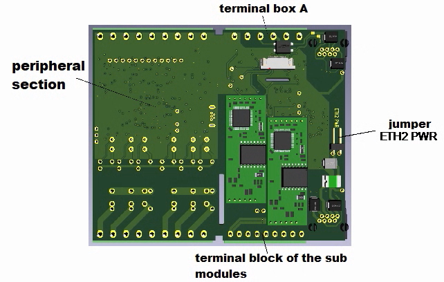
Fig. 1.1 Placing the ETH2 PWR jumper on the base plate of the base module after removing the bottom of the housing
Basic arrangement of Foxtrot 2
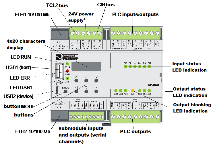
Fig 2. Basic module CP-2005 without WLAN1 or LTE1 (TXN 120 05.x1NSNN)

Fig 3. Basic module CP-2005 with LTE1 interface (TXN 120 05.x1NSLN)