
Mounting the TC800 module on a DIN rail with a system bus.
The TC800 module (this applies to both 12 mm and 24 mm wide modules) is mounted on a DIN rail using sliding latches that are operated by a lever on the underside of the module—see Fig. 1.
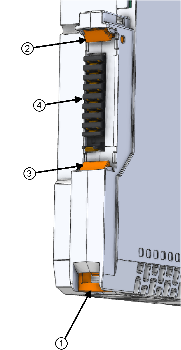
Fig. 1 the rear view of the TC800 module
- pull tab for securing and releasing the module from the DIN rail
- upper movable latch
- lower movable latch
- module bus connector
When mounting the module on a DIN rail with a system bus (which snaps into a standard 35 mm DIN rail with the red arrows pointing up—see Fig. 4), insert a screwdriver into the hole in the pull tab (see (1) in Fig. 2), then using the screwdriver as a lever, slide the pull tab away from the module until you hear a snapping sound (2). Then slide the module onto the DIN rail (3). After pressing the module firmly onto the DIN rail, snap the tab back into the module with your finger (4). The tab must not protrude from the module cover; otherwise, the module is not sufficiently secured and there is a risk of it coming loose or of poor electrical contact at the bus connector. The correct fixation and position of the module’s pull tab is shown in Fig. 3.
When installing the second and subsequent modules, it is necessary to insert the catches on the upper (5) and lower (6) sides of the module into the already installed adjacent module—this ensures the mechanical fixation of the modules and the rigidity of the entire assembly.
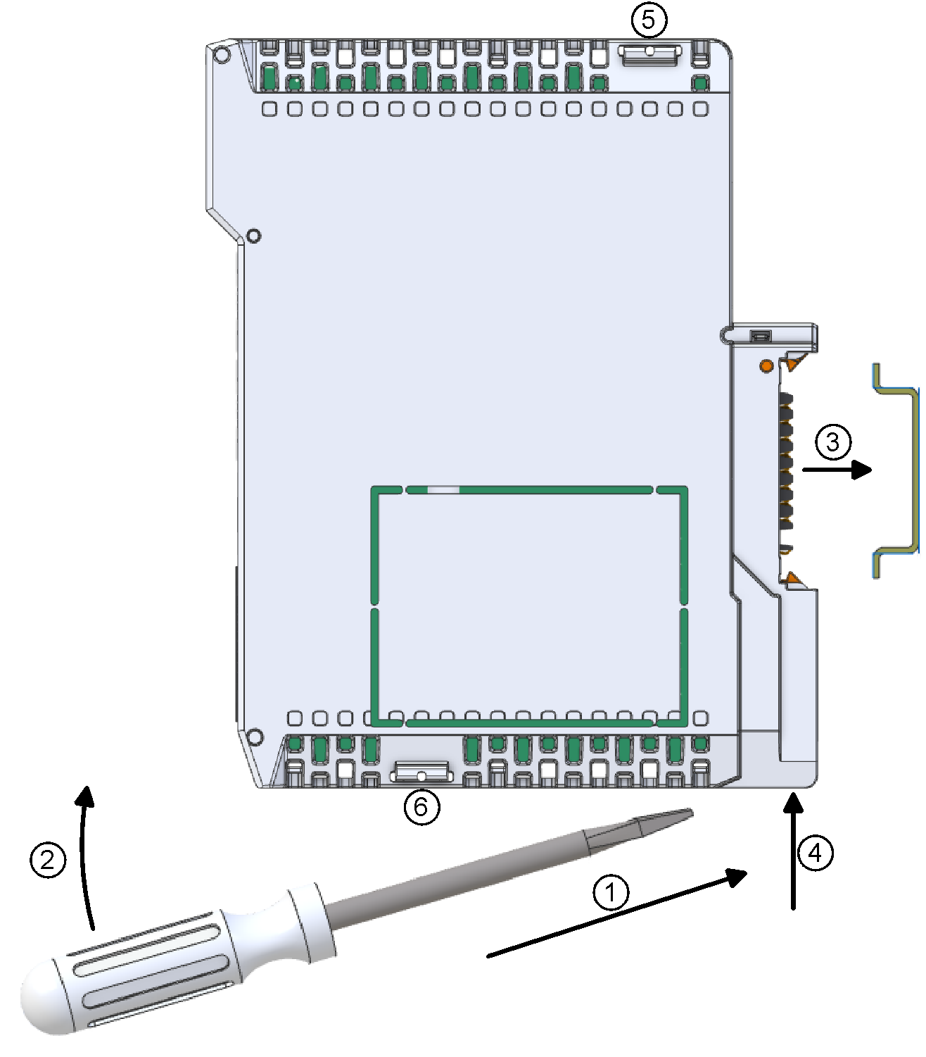
Fig. 2. Mounting the module on a DIN rail (for clarity, the system bus inside the DIN rail is not shown in the figure)
To remove the module, follow the same procedure: use a screwdriver to pull out the tab and remove the module from the DIN rail
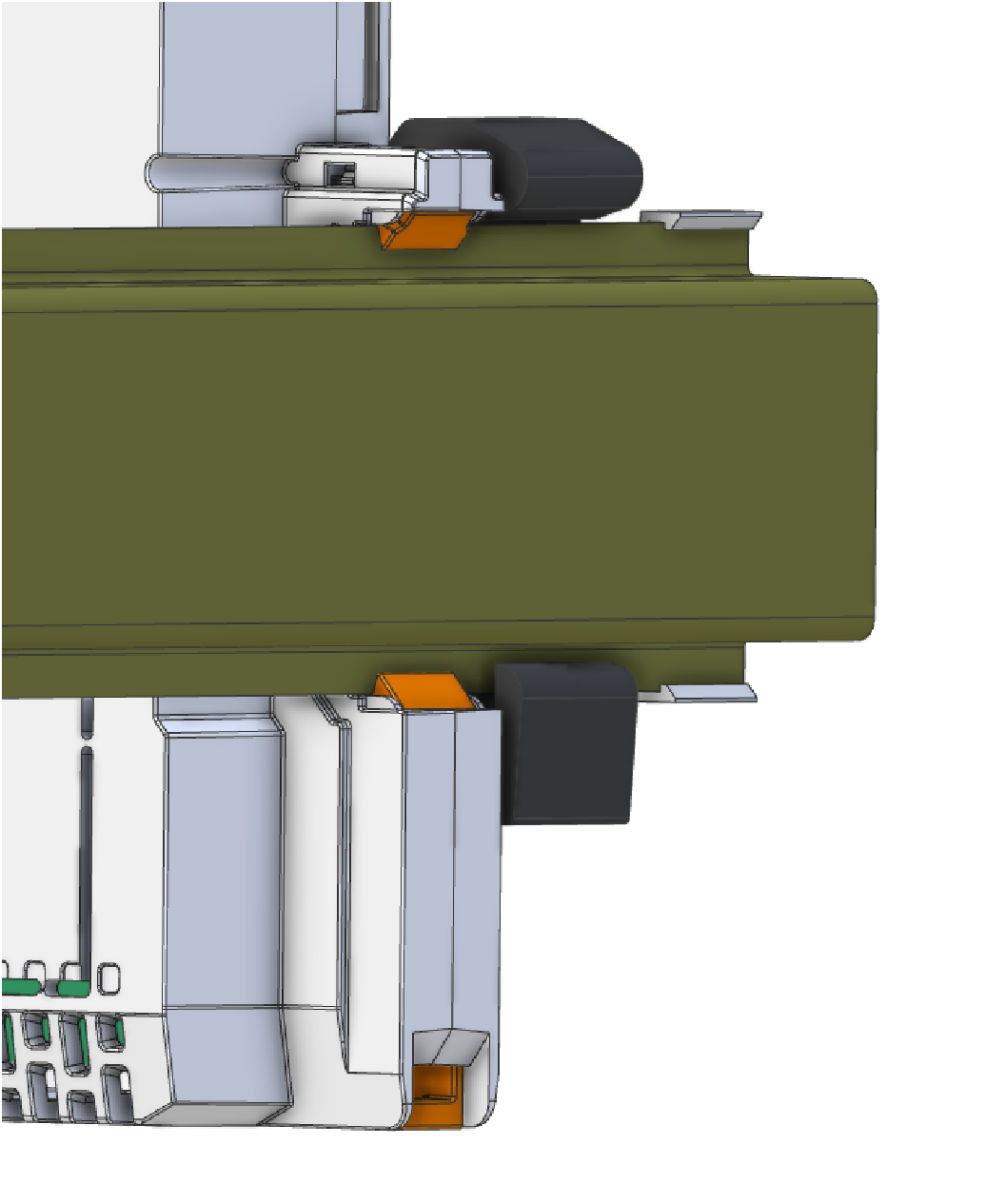
Fig. 3. Rear view of a module correctly mounted on a DIN rail
Complete TC800 System Configuration
A typical TC800 system configuration consists, from left to right, of a power supply module (PW-8901), a base module (CP-8001), and peripheral modules. The modules are mounted on the system bus (in Fig. 1, this is an RM-8940), and the remaining empty slots can be covered with blanking plates (set BS-C028).
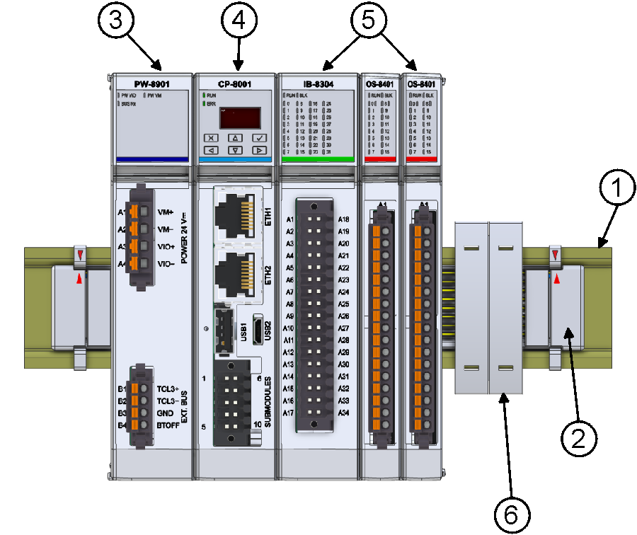
Fig. 4. The smallest TC800 PLC configuration
- Standard 35 mm DIN rail, 7.5 mm deep (not included with the TC800 system)
- System bus snapped into the DIN rail (here the shortest RM-8940, red arrows pointing up—see fig.)
- PW-8901 power supply module
- CP-8001 base module
- system peripheral modules
- blanking plates for empty slots (8 pcs. of 12 mm blanking plates are supplied as set BS-C028)