
Current transformers with a secondary output voltage of 333 mV use, for example, electricity meters C-EM-0300M and R-EM-0300M-A. It is not necessary to short-circuit this transformer during handling. The split core of the current transformer allows easy installation without the need to disconnect the wires of the measured system. Below are the transformers for installation on the conductor.
| classification |
Split measuring current transformer - xxx/333mV - cable |
|
| Model |
JC10F - xxx/333mV |
|
| Appearance |  |
|
| Output voltage | 333 mV | |
| Inner diameter |
10 mm |
|
| Nominal current |
30 A, 50 A, 75 A |
|
| Phase error | +1.5 ±1 ° | |
|
linearity error |
-1 ±1 % |
|
| Protection level | 2.2V0-P | |
| Protection level |
3.0V0 |
|
|
Installation category |
CATIII |
|
| Output terminals |
2 x M3, with cover |
|
|
Schemes |
|
|
| Operating temperatures | -20 ÷ 50 °C, up to 85 % RH, no condensation | |
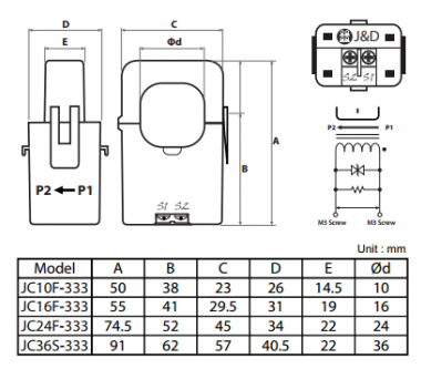
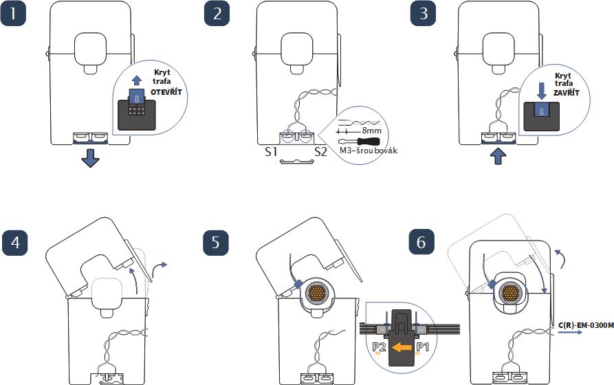
Fig. 1. Measuring transformer installation procedure
Notes(according to picture numbers):
- Remove the cover on the terminal board of the secondary side of the transformer.
- Screw insulated conductors with a maximum length of 100 cm, min. diameter 0.5 mm for connection to the electricity meter.
- Press the cover on the terminal board.
- Open the transformer cover and slide it onto the measured wire.
- Tighten the measured conductor with cable ties, the supply side (house connection) is on the P1 side, the measured load on the P2 side (marked on the side of the transformer).
- Snap the transformer cover (CAUTION for thorough closing and clicking, otherwise the transformer will be difficult to measure!) And connect the wires to the same marked terminals on the C (R) -EM-0300M electricity meter.
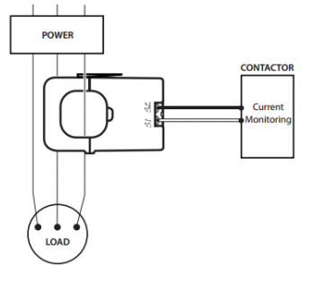
Fig. 2. Demonstration of the correct orientation of the transformer on the conductor in the direction from the supply (POWER) towards the load (LOAD)
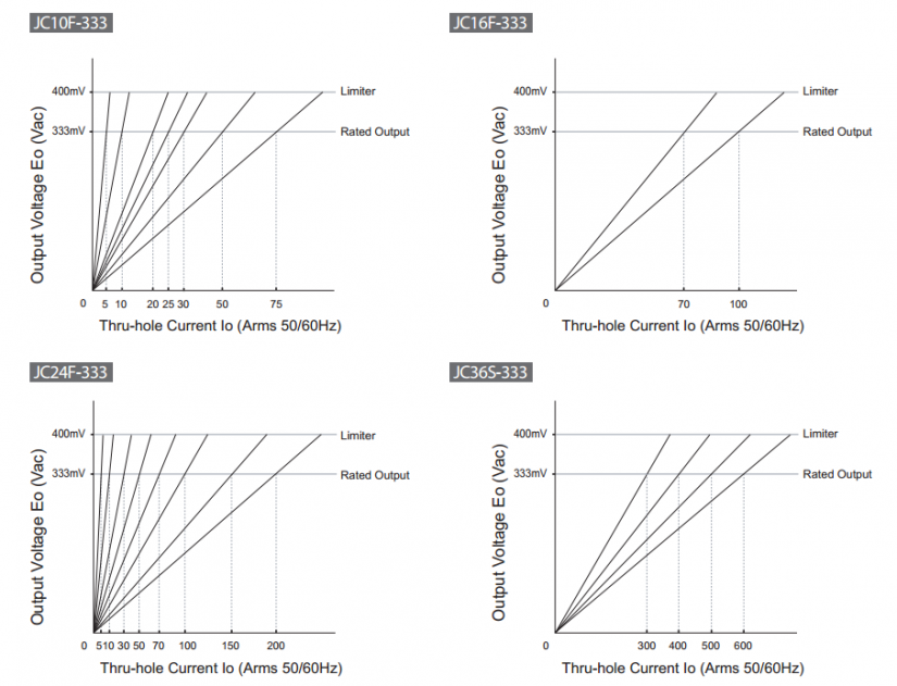
Fig. 3. Transformer output characteristics including permissible overload