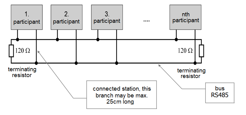
This type of interface makes it possible to connect up to 32 devices (some types of interfaces can be connected to several network participants) and it is sometimes referred to as a multi-drop interface.
It uses a half-duplex system, which means using less wires in the cable. It is resistant to interference and allows a serial line as long as 1.2 km to be built (without a repeater). In order for this interface to function properly it is necessary to provide 120 Ω terminating resistors at either end of the cable.
Any 120 Ω minimum 0.25 W resistor can serve as a terminating resistor; it must always be located at terminals at both ends of the network. In FOXTROT systems this requirement addressed by termination circuits mounted on the RS-485 serial interface submodules, which contain a 120 Ω resistor and circuits for correct definition of the idle state of the line.
The line must maintain the character of the bus, i.e. the cable must always be routed from the station to the next station. If it is necessary to make a branch, its length must not exceed 25 cm (there must be no termination resistor on this branch!).

Fig. 1. The basic connection of the RS-485 communication line
Notes:
-
The shielding is always connected only on one side of the line.
-
The last control system on the bus should be fitted with a 120 Ω resistor (if connecting only two systems, the resistors or termination circuits should be connected at both ends of the cable).
-
You should always interconnect identically marked terminals TxRx + (somewhere TxRx), also TxRx- (TxRxB).
In large networks a shift of communication interfaces potentials can occur due to improper installation. This problem can be partly removed by connecting the GND terminals of individual network participants (but this only deals with the consequences, not the causes). A better solution is to use a galvanic isolation of individual network participants (the MR interface submodules always provide galvanic isolation of the line); an alternative solution is to find and eliminate the cause of the potential shift.
Technical parameters of the RS-485 interface
|
Maximum data transfer rate |
about 1 Mb/s |
|
Maximum length of the line |
1,200 m 1) |
|
Output level (differential levels) |
Maximum ± 6 V |
1) The maximum rate of data transfer is not reached with the maximum length of the line.
The cables for communications networks should always be routed away from direct contact with power cables (the minimum recommended distance is 15 cm), they should avoid places with strong interference or with a risk of discharges. Communication interfaces can be lead together with cables for analogue signals, other data networks, etc.
When laying cables in an environment with a risk of interference, or when the distances are greater, you should use shielded cables (for the principle of shielding see the relevant chapter).
