
The expansion module IB-1301 is designed to scan up to twelve 24 VDC binary signals with a common terminal (plus or minus, according to the wiring), type 1 (in accordance with EN 61131).
The DI0 ÷ DI3 inputs allow the implementation of special functions identical with the inputs of the CP-1004 basic module (the functions and input modes are identical with the DI0 ÷ DI3 inputs of the CP-1004 module). For detailed information and examples of connections, see Chapter 2.7.3.1 Special functions of binary inputs in the CP -1004 module.
The DI4 ÷ DI11 inputs are standard binary inputs with a 5 ms input filter.
The inputs are galvanically isolated from the internal circuits (power supply and communication to the basic module) and groups of inputs are separated from one another; the status of each input is indicated on the front panel of the module.
The DI0 ÷ DI7 binary inputs
|
|
DI0 ÷ DI3 |
DI4 ÷ DI7 |
|
Input type |
Type 1 |
|
|
Input voltage for Log. 0 |
max. +5 VDC |
|
|
Input voltage for log.1 |
min. +15 VDC, typically +24 VDC, max. +30 VDC |
|
|
Input current in log. 1 |
typically 10 mA |
typically 5 mA |
|
The minimum width of the captured pulse |
50 μs |
- |
The DI0 ÷ DI 3 counter inputs
|
Max. input frequency |
5 kHz |
|
The minimum width of the captured pulse |
50 μs |
|
Incremental sensor: |
|
|
Max. frequency of symmetric signal V, G |
1.25 kHz |
|
Pulse width (V, G, NI, MD) |
min. 50 µs |
|
Pulse length, period and phase shift measurement: |
|
|
Input frequency |
0.1 ÷ 5,000 Hz |
|
Pulse width |
50 ÷ 10,000,000 µs |
Basic parameters
|
Supply voltage |
24 VDC, +25%, –15% |
|
Typical power consumption |
1 W |
|
Maximum power consumption |
2 W |
The connectors of the module are standard removable ones with a cage terminal in the removable part with 5.08mm spacing. A flat-head screwdriver with the tip width of 3.5mm is recommended for manipulation with the terminal. Detailed parameters of the terminals are specified in Chapter 13.3.1 Connectors with screw terminals, spacing 5.08mm, modules on a DIN rail.
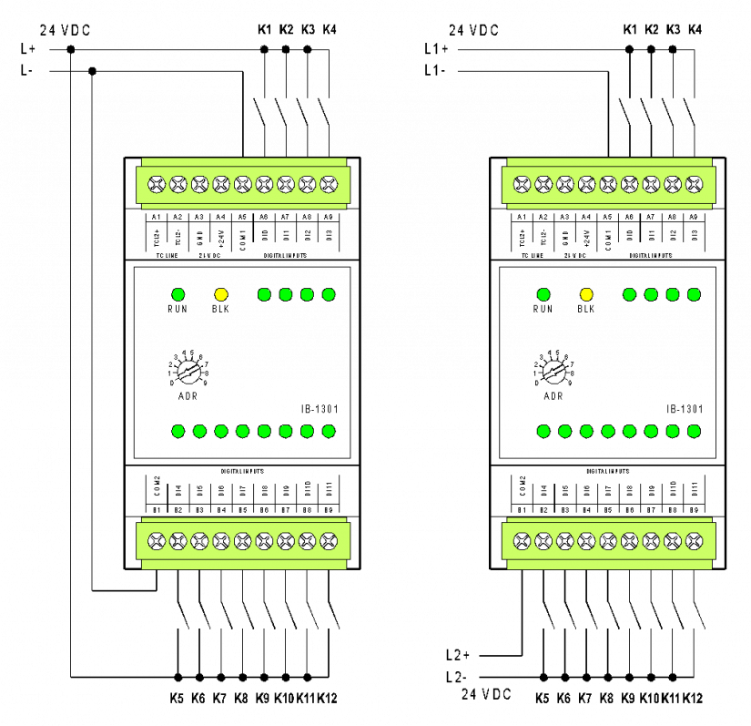
Fig. 1 The basic wiring diagram of the IB-1301 module
Wiring notes:
-
The DI0 ÷ DI3 inputs make it possible to implement special functions (connection of incremental encoders, counters, etc.); for detailed information, see Chapter 2.7.3.1.
-
Groups of inputs (the DI0 ÷ 3 and the DI4 ÷ 11) are galvanically isolated from each other.
-
In the left example, the inputs are connected with a common negative terminal, the right diagram shows a connection via a common negative terminal for the DI0 ÷ DI3 inputs and a common positive terminal for the DI4 ÷ DI11 inputs.