
The CP-1005 is the basic module of the Foxtrot control system. A standard configuration of the module is in a 6M housing on a DIN rail (for the housing dimensions, see Chapter 6M housing on a DIN rail), and it is fitted with six removable terminal blocks.
The layout:
Power supply 24 VDC, power consumption typically 3 W, max. 8 W (see Chapter 2.2)
AI0 ÷ AI5 6 analogue inputs, without galvanic isolation, with an optional function of a binary input:
ranges: 10 V, 0÷20 mA, 4÷20 mA, Ni1000, Pt100, OV1000, OV100, DI 24 VDC
AO0 ÷ AO1 2 analogue outputs, without galvanic isolation, range 0 ÷10 V
DO0 ÷ DO5 6 relay outputs, with galvanic isolation from other circuits
ETH Ethernet 10/100 Mbit (a standard RJ-45 connector), with galvanic isolation from other circuits, see Chapter 2.4.1
CH1 Serial channel, with fixed RS232 interface, without galvanic isolation, see Chap. 2.3.1
CH2 Serial channel, with a possibility of fitting with standard submodules, see Chapter 2.3.3
The analogue inputs AI0 ÷ AI5
|
Voltage ranges |
0 ÷ 0.5 V 0 ÷ 1 V 0 ÷ 2 V 0 ÷ 5 V 0 ÷ 10 V |
|
Temperature sensor Pt100, W100=1.385 or 1,391 |
-90 °C ÷ +400 °C |
|
Temperature sensor Pt1000, W100=1.385 or 1.391 |
-90 °C ÷ +400 °C |
|
Temperature sensor Ni1000, W100=1.500 or 1.617 |
-60 °C ÷ +200 °C |
|
Temperature sensor NTC 12k |
-40 °C ÷ +125 °C |
|
Temperature sensor KTY81-121 |
-55 °C ÷ +125 °C |
|
Resistance ranges |
0 ÷ 1 kΩ 0 ÷ 2 kΩ 0 ÷ 200 kΩ |
|
Current ranges |
0 ÷ 20 mA 4 ÷ 20mA |
|
Input resistance for voltage ranges |
> 20 kΩ (ranges 10 V, 5 V) > 50 kΩ (ranges 2 V, 1 V, 0.5 V) |
|
Input resistance for current ranges |
100 Ω |
|
Internal voltage for power supply of resistance sensors |
7.27 V |
|
Conversion time of channel |
typically 80 μs |
|
Recovery time of each channel value |
typically 480 μs |
|
Binary inputs |
|
|
Input voltage for Log.0 |
max. +5 VDC |
|
Input voltage for Log.1 |
min. +15 VDC typically +24 VDC max. +30 VDC |
|
Input current in log. 1 |
typically 5 mA |
|
The minimum width of the captured pulse |
500 μs |
The analogue output AO0, AO1
|
Output range |
0 ÷ 10 V |
|
Maximum output value |
105 % of the output range upper limit |
|
Maximum output current |
10 mA |
|
Maximum load capacity |
50 nF |
The relay outputs
DO0 ÷ DO2, outputs with a common terminal, continuous current in the 3 A output, inrush 5 A, max.continuous current in common terminal COM1 is 10 A, detailed information on relay contacts
Isolation voltage among groups of outputs and from other circuits is 3,750 VAC, i.e. safe isolation of circuits
DO3 ÷ DO5, outputs with a common terminal, continuous current in 3 A output, inrush 5 A, max.continuous current in common terminal COM2 is 10 A, detailed information on relay contacts
For principles of protection and usage for capacitive and inductive loads, see Chapter 13.7.1 Protection of output elements (relays,...).
The terminal block of the basic module is made up of connectors with a cage terminal with the spacing of 5.08 mm. Detailed parameters of the terminals are specified in Chapter 13.3.1 Connectors with screw terminals, spacing 5.08mm, modules on a DIN rail
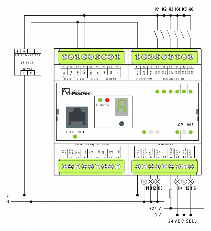
Fig. 1 A standard example of the CP-1005 basic module wiring
Wiring notes:
-
Groups of relay outputs (DO0 ÷ 2 and DO3 ÷ 5) can switch circuits powered by different sources. The groups are separated by isolation corresponding to a safe circuit isolation.
-
Optional functions of AI inputs are set from the programming environment and the jumpers located in the bottom of the box (above a DIN-rail holder), wiring examples are shown in the following chapters.
-
The TCL2 bus has fixed termination inside the basic module so it must always be located at the end of the bus line (see Chapter 3.2)
-
The module power supply, the TCL2 interface, the CIB and the CH1 have a common signal ground, a GND terminal (A3 terminal). This terminal is connected with a common terminal AI/AO (terminal B1).
-
The analogue inputs AI0÷AI5 are configured as inputs with a common negative terminal GND.
-
The terminals A3 and B1 (GND) should not be interconnected (they are connected by internal circuits). When the power to CP and input circuits is supplied from one source (see the example), the B1 terminal is not used. When powering the DI input circuits from a separate source, then the negative terminal of the source should be connected to the B1 terminal.
The following diagram.2 shows the connection of various analogue sources and sensors, as well as potential free contacts:
The AI0 input voltage - e.g.. 0÷10V voltage is connected, positive terminal on AI0, negative terminal on GND,
The AI1 current input, i.e. the source of current is connected, e.g. 4÷20 mA (powering the loop must be provided by an external source, see an example in Chapter 11.3.9),
The AI2 , AI3 inputs are passive – two-wire resistance sensors (RTD) are connected, or resistive transmitters,
The AI4 and AI5 inputs are digital (i.e. they are evaluated as DI4 and DI5), standard 24 V inputs with common negative terminal GND,
the AO0 and AO1 voltage outputs 0÷10V, the diagrams show the connected loads Rz (controlled circuits).
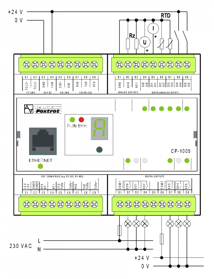
Fig. 2 An example of wiring the basic module CP-1005 analogue inputs and outputs.