
The DI0, DI1 (counter 1) and the DI2, DI3 (counter 2) binary inputs can be set - in addition to the function of standard inputs - to one of the special functions, allowing the connection of a positioning incremental encoder, application of fast counters, measuring the period and phase shift (e.g. for the phase-locking of a generator in small hydro plants ), etc.
Individual functions are described in detail in the documentation TXV 004 10, here is a Table with an overview of examples of specific terminal connections.
Tab. 1 Counter 1
|
mode |
function |
DI0 |
DI1 |
DI2 |
DI3 |
An example |
|
00 |
The counter is off (inputs DI0 and DI1 – standard binary inputs) |
DI0 |
DI1 |
According to counter 2 |
|
|
|
01 |
One unidirectional counter |
CI1 |
- |
According to counter 2 |
||
|
02 |
Two unidirectional counters |
CI1 |
CI2 |
According to counter 2 |
Fig. 2 | |
|
04 |
Bidirectional counter |
UP1 |
DN1 |
According to counter 2 |
|
|
|
05 |
Counter with direction control |
CI1 |
U/D1 |
According to counter 2 |
|
|
|
08 |
Incremental encoder (without zeroing and capturing) |
V1 |
G1 |
According to counter 2 |
||
|
14 |
Bidirectional counter with zeroing and capturing |
UP |
DN |
RES |
MEM |
|
|
15 |
Counter with direction control with zeroing and capturing |
CI |
U/D |
RES |
MEM |
|
|
18 |
Incremental encoder with zeroing and capturing |
V |
G |
NI |
MD |
Fig. 4 |
|
1C |
Pulse length measurement |
IN1 |
IN2 |
IN3 |
IN4 |
|
|
1D |
Period and phase shift measurement |
PER1 |
PER2 |
PER3 |
PER4 |
|
Tab. 2 Counter 2
|
mode |
function |
DI0 |
DI1 |
DI2 |
DI3 |
An example |
|
00 |
The counter is off (inputs DI0 and DI1 – standard binary inputs) |
According to counter 1 |
DI2 |
DI3 |
|
|
|
01 |
One unidirectional counter |
According to counter 1 |
CI2 |
- |
Fig. 1 | |
|
02 |
Two unidirectional counters |
According to counter 1 |
CI3 |
CI4 |
Fig. 2 | |
|
04 |
Bidirectional counter |
According to counter 1 |
UP2 |
DN2 |
|
|
|
05 |
Counter with direction control |
According to counter 1 |
CI2 |
U/D2 |
|
|
|
08 |
Incremental encoder (without zeroing and capturing) |
According to counter 1 |
V2 |
G2 |
Fig. 3 | |
Tab. 3 The DI0 ÷ D I3 counter inputs
|
Max. Input frequency |
5 kHz |
|
The minimum width of the captured pulse |
50 μs |
|
Incremental sensor: |
|
|
Max. frequency of symmetric signal V, G |
5 kHz |
|
Pulse width (V, G, NI, MD) |
min. 50 µs |
|
Pulse length, period and phase shift measurement: |
|
|
Input frequency |
0.1 ÷ 5,000 Hz |
|
Pulse width |
50 ÷ 10,000,000 µs |
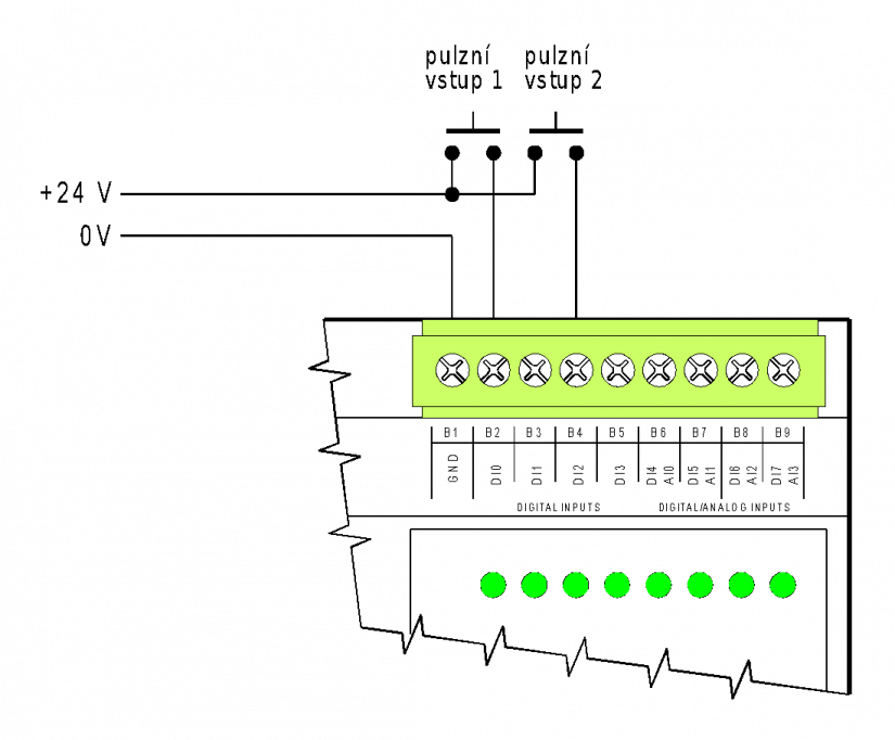
Fig. 1 An example of connecting a sensor with a pulse output (for counter 1 and counter 2)
Wiring notes:
-
The inputs are implemented with a common terminal - (N.B.: the GND terminal!). The terminal is galvanically connected with the negative power supply terminal and the signal ground of the TCL2, CIB and CH1 interface).
-
The inputs require a connection of the sensor with the pulse output (eliminating flickers).
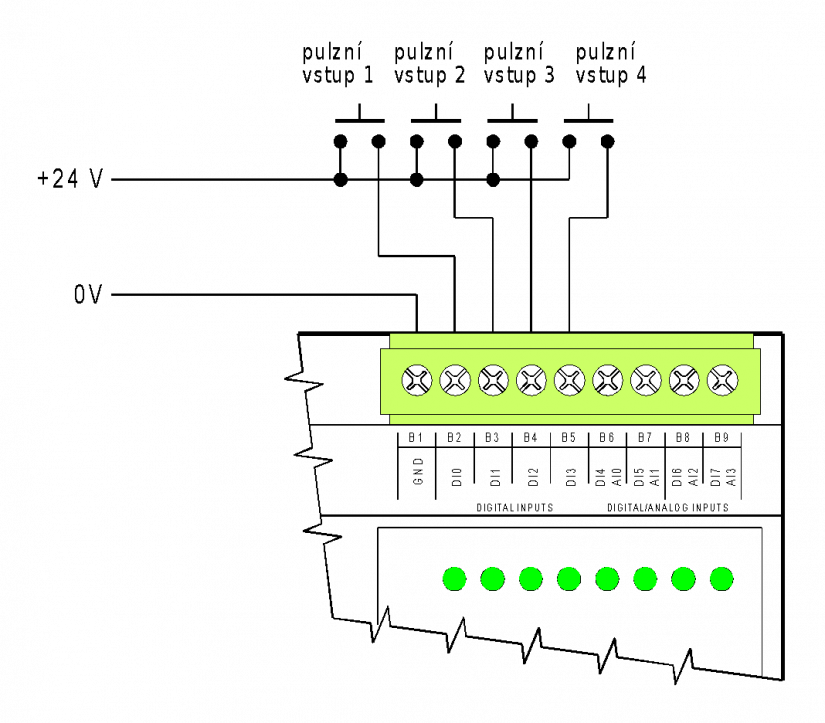
Fig. 2 An example of connecting a sensor with the pulse output (for counters 1 up to counter 4)
Wiring notes:
-
The inputs are implemented with a common terminal - (N.B.: the GND terminal!). The terminal is galvanically connected with the negative power supply terminal and the signal ground of interface TCL2, CIB and CH1).
-
The inputs require a connection of the sensor with the pulse output (with avoiding flickers).
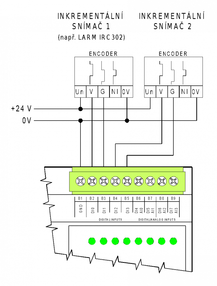
Fig. 3 An example of connecting incremental encoders (counter 1 and counter 2)
Wiring notes:
-
The inputs are implemented with a common terminal - (N.B.: the GND terminal!). The terminal is galvanically connected with the negative power supply terminal and the signal ground of interface TCL2, CIB and CH1).
-
The module is designed to connect incremental encoders (rotary, linear) with an output of 24 V (it cannot be connected to sensors with 5 V output!). In this mode, only both tracks of the sensor are captured. A zero pulse and the measuring probe (the capture input) cannot be evaluated.
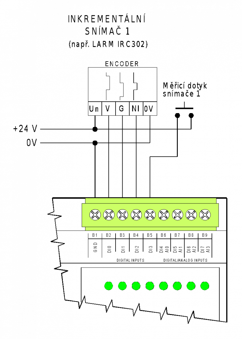
Fig. 4 An example of connecting an incremental encoder with zeroing and capturing
Wiring notes:
-
The inputs are implemented with a common terminal - (N.B.: the GND terminal!). The terminal is galvanically connected with the negative power supply terminal and the signal ground of interface TCL2, CIB and CH1).
-
The module is designed to connect incremental encoders (rotary, linear) with an output of 24 V (it cannot be connected to sensors with 5 V output!). In this mode, both tracks, zero pulse and the measurement probe of the connected sensor are captured.