
The CP-1004 basic module is the smallest independent control system in the Foxtrot series. A standard configuration of the module is in a 6M housing on a DIN rail (for the housing dimensions, see Chapter 6M housing on a DIN rail), and it is fitted with six removable terminal blocks.
The layout:
Power supply 24 VDC, power consumption typically 3 W, max. 8 W (see Chapter 2.2)
DI0 ÷ 7 8 binary inputs, without galvanic isolation
DI0 ÷ DI3 optional special functions (see Chapter 2.7.3.1),
DI4 ÷ DI7 optional analogue inputs 0÷10 V (positive input terminal AI0÷AI3)
DO0 ÷ DO5 6 relay outputs, with galvanic isolation from other circuits
ETH Ethernet 10/100 Mbit (a standard RJ-45 connector), with galvanic isolation from other circuits, see Chapter 2.4.1
CH1 Serial channel, with fixed RS-232 interface, without galvanic isolation, see Chap. 2.3.1
CH2 Serial channel, with a possibility of fitting with standard submodules, see Chapter 2.3.3
The AI0 ÷ AI3 analogue inputs
|
Range |
0 ÷ 10 V |
|
Input resistance |
about 6.9 kΩ |
|
Conversion time |
20 μs |
The DI0 ÷ DI7 binary inputs
|
Input type |
Type 1 |
|
Input voltage for Log. 0 |
max. +5 VDC |
|
Input voltage for log.1 |
min. +15 VDC, typically +24 VDC, max. +30 VDC |
|
The minimum width of the captured pulse |
50 μs |
|
Max. input frequency (DI0 ÷ DI3 inputs) |
5 kHz |
The relay outputs
The DO0 ÷ DO2, outputs with a common terminal, continuous current in the 3 A output, inrush 5 A, max.continuous current in common terminal COM1 is 10A, detailed information on relay contacts.
Isolation voltage among groups of outputs and from other circuits is 3750 VAC, i.e. safe isolation of circuits.
The DO3 ÷ DO5 outputs with a common terminal, continuous current in 3 A output, inrush 5A, max.continuous current in common terminal COM2 is 10A, detailed information on relay contacts.
The principles of protection and application for capacitative and inductive loads are defined in Chapter 13.7.1 Protection of output elements (relay, ...).
The terminal block of the basic module is made up of connectors witha cage terminal with spacing 5.08 mm. Detailed parameters of the terminal are specified in Chapter 13.3.1 Connectors with screw terminals, spacing 5.08mm, modules on a DIN rail
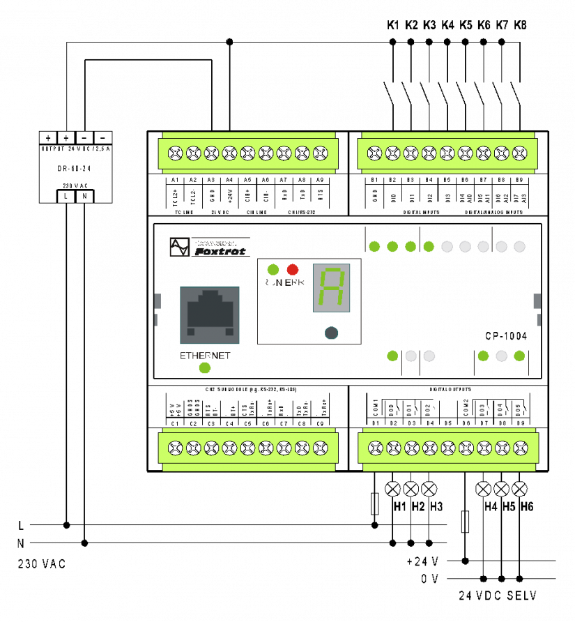
Fig. 1 A standard example of the CP-1004 basic module wiring
Wiring notes:
-
Groups of relay outputs (DO0 ÷ 2 and DO3 ÷ 5) can switch circuits powered by different sources. The groups are separated by isolation corresponding to a safe circuit isolation.
-
Optional functions of the DI/AI inputs are set from the programming environment, and the wiring examples are shown in the following chapters.
-
The TCL2 bus is firmly terminated in the basic module and it must always be at the end of the bus line (see Chapter 3.3 The TCL2 bus – principles of design and installation).
-
The module power supply, the TCL2 interface, the CIB and the CH1 have a common signal ground, a GND terminal (the A3 terminal). This terminal is connected to a common terminal DI/AI (the B1 terminal).
-
The analogue inputs AI0÷AI3 are configured as inputs with a common negative terminal GND.
-
The A3 and B1 terminals (GND) should not be connected with each other (they are connected via internal circuits). In powering CP and the input circuits from one source (see the example), the B1 terminal is not used at all. When powering the DI input circuits from a separate source, then the negative terminal of the source should be connected to the B1 terminal (see Fig. 2).
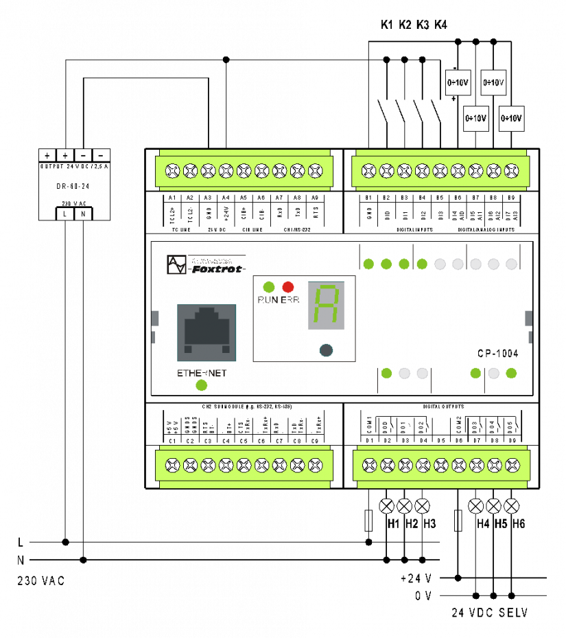
Fig. 2 An example of wiring the CP-1004 module analogue inputs