
If the Foxtrot (in this case CP-1000) control system is also utilized for electronic security signalization, it is vital to use a battery backup. The power supply must be able to supply power to the electronic security system in all its modes for the required time, while the power supply must provide charging of the connected backup batteries. The PS2-60/27 power supply with 27.2 VDC output voltage is specified to power the whole system and to charge the backup batteries. The supply is also fitted with a 12 VDC output, with max. 300 mA, for powering the detectors of the electronic security system. This supply voltage is active even when the application is running from the connected batteries. For a backup, it is necessary to use two 12 VDC sealed lead-acid type batteries (typically with a capacity of 7 Ah up to 18 Ah), connected in series – see the figure below.
The presence of 230 VAC mains voltage is monitored by the IN 230 VAC input (the mains voltage is connected to F1 and F2 terminals). The basic module also measures the value of the main power supply voltage (i.e. the voltage at the C connector). The state of the IN 230 VAC input and the level of supply voltage are indicators of both the presence of the mains 230 VAC voltage and the state of the batteries (if they are used) by measuring their voltage; a warning signal will be sent in time before their discharge (as an SMS message , etc.).
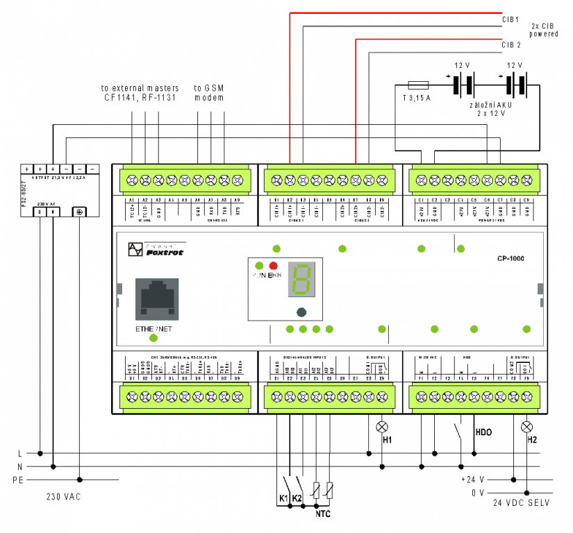
Fig. 2 An example of the CP-1000 power supply connection with a backup of the system supply voltage.
Notes:
-
The power supply must be stabilized 27.2 VDC, fulfilling the SELV requirements and designed to charge the connected batteries, usually the PS2-60/27. The power consumption of the CP-1000 is the sum of its own consumption (typically 4W) and the total power consumption of all CFox modules connected to both CIB branches.
-
The battery lifetime is approx. 3-4 years, but it decreases significantly with increasing ambient temperature, so it is advisable to place the batteries in a cooler location. It should be placed in the lowest possible location in the distribution cabinet (e.g. on the bottom of the housing).
-
In the terminal block B there is an output of both CIB branches including the power supply with a maximum current of 1A for each branch.
-
The AI/DI0 to AI/DI3 inputs are universal (contact, NTC temperature sensor, Pt1000, Ni1000), the inputs do not have the function of "capturing short pulses", which means that the evaluated input state length must exceed that of the programme cycle (200 ms is usually enough).
-
The IN 230 VAC input (F1 and F2 terminals) is designed to monitor the presence of 230V mains power supply. It is a standard 230VAC input, with galvanic isolation.
-
The ripple control input (F4 and F5 terminals) is for the ripple signal coming from the utility distribution grid. This input can withstand even a badly connected ripple control (ripple signal coming from the grid) in the household installation without being damaged.
-
The DO0 and DO1 outputs are standard electromechanical 3A contact relays, with galvanic isolation from other circuits.
 Wiring according to Fig. .2. does not permit using a more powerful type of power supply, because during a power outage and the battery discharge, the supply (and charging) current increases to a point when the fuse on the power supply lead to the CP-1000 blows. Subsequently, the system works further only powered by batteries, which are not being recharged.