
If the system controls power elements with inductive character (valves, contactors, larger relays, smaller motors, etc.), you should always ensure the most effective suppression of formation and radiation of interference field. Therefore a suppression element should always be mounted directly on the terminals of the switched element. The cables between the suppression element and the protected device must be as short as possible.
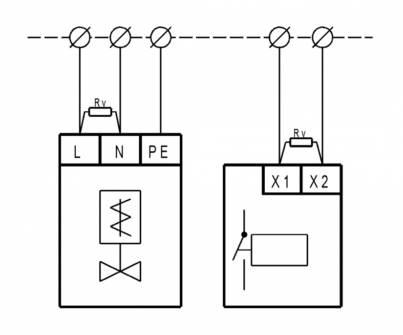
Fig. 1. An example of connecting the suppression element to the load
Notes:
-
Always install the suppression components as close to the load (the interference source) as possible.
-
Suitable suppressor elements are described in the following tables.
Table .1: Recommended methods of handling the inductive load.
|
Nominal voltage |
Description |
Type |
Wiring diagram of the element |
The voltage on the load curve |
|
DC and AC : typically 24 VDC 24 VAC 230 VAC |
The most commonly used, less suitable if the network is bad, the drawback of ageing. |
VARISTOR |
|
|
|
DC and AC : typically 24 VDC 24 VAC 230 VAC |
Universal usage for a larger range of voltages, suitable for bad networks. |
RC member |
|
|
|
DC typically 24 VDC
|
Only for DC circuits, drop-out delay of the protected relay should be counted with (dozens of ms); it can be mitigated by a resistor in a series. |
DIODE |
|
|


When selecting varistors, you should use the type for the appropriate nominal voltage of the circuit (e.g. at 24 VAC, a varistor for 45 VAC voltage must be used). There are sets of varistors available ready to use for standard voltage values. For the list of the sets, see Table .2.
For certain voltages and load currents it is possible to calculate the optimum values of resistor and capacitor, that each RC element consists of (a diagram for the calculation is shown in Fig. 2).
Typical applications with the Foxtrot systems are supported with ready-to-use sets. The RC elements are provided for a greater range of voltage, and they are already encased with two wire outlets for immediate use.
They are mostly used for interference suppression of relay coils and contactors. Standard diodes (e.g.1N4007) can be used for typical currents of dozens of mA.
A diagram to determine the value of the RC element.
Using a graph, it is possible to determine the values of RC members for a specific circuit parameters.

Fig. 2. A diagram to determine the value of the RC member
The value of C follows directly from the switched current (the left axis).
The value of R can be found by leading a straight line through the respective points of I axis of the U curve; the value of resistance should be subtracted at the intersection of the line with the R axis (the right axis).
The measured or estimated value of the overvoltage resulting from the switching off the circuit with an inductive load (typically 2÷5 times nominal voltage) should be substituted as the U voltage value.
An example: U = 90 V, I = 1 A
What follows for the condenser capacitance is the value 0.1 µF; the resistance value can be determined by a straight line drawn to 10 Ω.
This method is too complicated for common applications, so we supply directly the RC members that suit most applications (contactors, valves, etc.). Their summary in listed in the Table. 2.
Tab. 2. A diagram to determine the value of the RC member
|
Name |
The order number |
Table of contents |
Nominal voltage of the load |
|
The interference suppression set |
TXF 680 00 |
8x varistor |
24 VDC, 24 VAC |
|
The interference suppression set |
TXF 680 01 |
8x varistor |
48 VDC, 48 VAC |
|
The interference suppression set |
TXF 680 02 |
8x varistor |
115 VAC |
|
The interference suppression set |
TXF 680 03 |
8x varistor |
230 VAC |
|
The interference suppression set |
TXF 680 04 |
8x RC member |
24 ÷ 48 VDC, 24 ÷ 48 VAC |
|
The interference suppression set |
TXF 680 05 |
8x RC member |
115 ÷ 230 VAC |
Tab. 3. The parameters of varistors used in interference suppression sets
|
the energy that can be captured by the I2t varistor (t is the duration of the blanking pulse in ms) |
< 80 |
|
current in varistor I |
< 25 A |
|
medium value of power loss P |
< 0.6 W |