
The module is designed to control AC charging of electric vehicles (EV) from conventional grid 230/400 VAC.
The module for charging control utilizes the CP (Control Pilot) signals and PP (Proximity function) signals in accordance with the EN 61851-1 standard. Both signals are terminated together with the ground terminal on the B connector of the module.
This connector also contains the terminal of the DO2 relay output switching the power contactor, which connects the mains voltage to the charging cable.
The PP signal is used by the car electronics as information about the connected charging cable; the signal is controlled by the C-EV-0302M module.
The CP signal is used both to control the charging current in the range from about 5% to 100%, while providing feedback on the charging and connections status such as "the car is connected", "charging", charging while cooling", "fault".This information is transmitted by the C-EV-0302M module via the bus to the system for further processing, and is also displayed by LED indicators on its panel.
The module is equipped with two universal inputs AI/DI1 and AI/DI 2, which allow you e.g. to connect control buttons START and STOP; you can place them on the door of the cabinet with control electronics to control local charging (e.g. after arrival or departure), or you can use the inputs to connect temperature sensors and the like.The third input DI3 is intended primarily for the connection of the S0 electricity meter output for applications, where you want to keep track of the amount of energy supplied to the vehicle, or to have a better overview of charging, or it may be used as a standard binary input.
The module is also equipped with a binary output DO1 intended only for a LED indicator, which can be placed on the cabinet door next to the buttons to indicate charging in progress.
The parameters of the connectors used are listed in Chap. 13.3.1
The module is in a 3M box.
The basic parameters of inputs and outputs:
|
The type of input (connected sensor), inputs AI/DI1, AI/DI2 |
The range of measured values |
|
Pt1000 |
-90 °C ÷ +320 °C |
|
Ni1000 |
-60 °C ÷ +200 °C |
|
NTC 12k |
-40 °C ÷ +125 °C |
|
KTY81-121 |
-55 °C ÷ +125 °C |
|
Maximum resistance 100 kΩ |
0 ÷ 100 kΩ |
|
Voltage 2 V |
0 ÷ 2100 mV |
|
The input resistance of inputs for voltage ranges. |
approx. 100 kΩ, see the Fig. internal wiring |
|
The type of input (a connected sensor), the input DI3 |
The range of measured values |
|
16-bit pulse counter (electricity meter with an S0 output) |
> 30 ms pulse, frequency max. 20 Hz |
|
The input excitation voltage |
15 V |
|
Input current in log. 1 |
Typically 5 mA |
|
The DO1 output |
|
|
Nominal output voltage UJM |
15 VDC |
|
Maximum output current |
20 mA |
The DO2 output is fitted with a standard 5 A relay, switching contact.
|
Outputs CP, PP |
|
|
Nominal voltage output voltage |
±12 VDC |
|
Maximum output current |
30 mA |
|
Signal curves on the outputs |
In accordance with EN 61851-1 |
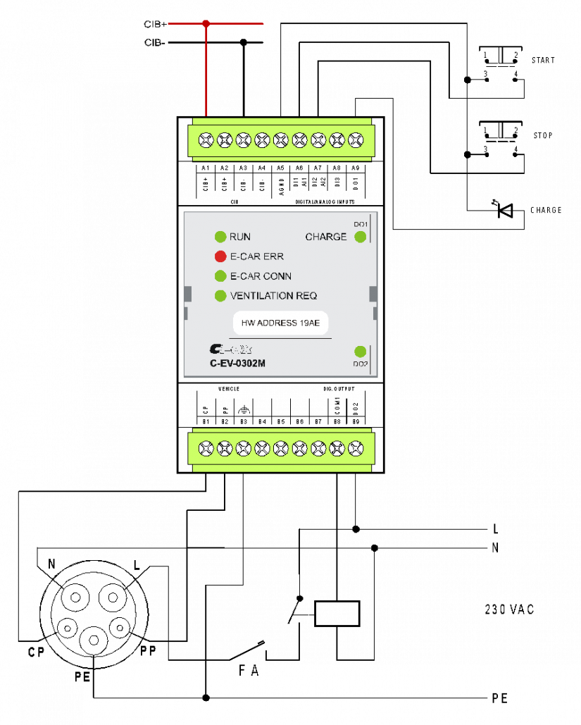
Fig. 1. An example of connecting the C-EV-0302M module.