
The design of the module is suitable for controlling rooms, hotel rooms (lighting, heating, sockets, etc.) and other applications, where the combination of inputs and outputs can be utilized - in particular with the requirement to switch loads with a capacitive character: lighting circuits, socket circuits, etc.
The module contains 8 binary inputs for connecting switching contacts, 3 analogue inputs for connecting resistive sensors, 8 relay outputs and one voltage analogue output (0 ÷ 12 V). Individual re lay outputs can be manually locally controlled via the buttons on the module panel.
The module is fitted with relays designed to switch capacitive loads, 4x relays with a 16 A contact and 4 relays with a 10 A contact.
Powering the module
If you connect an external 24 V power supply to terminals A3 and A4, the powering will be automatically switched from the CIB to this external source. To switch the power supply, a higher voltage than 19.2 VDC must be brought to the A3 terminal.
If the module is powered from an external power supply (terminals A3, A4), the CIB line could be overloaded during a power failure (e. g. if there is a power outage in the 230 VAC grid as well as in the CIB power supply backup).The module in this configuration allows activation of the mode, which blocks (opens) the switched contacts during a power failure; it prevents overloading the line (the module power consumption decreases to 25mA).
The basic parameters of inputs and outputs:
|
The type of input (a connected sensor), the inputs AI1, AI2, AI3 |
The range of measured values |
|
PT1000 |
-90 °C ÷ +320 °C |
|
Ni1000 |
-60 °C ÷ +200 °C |
|
NTC 12k |
-40 °C ÷ +125 °C |
|
KTY81-121 |
-55 °C ÷ +125 °C |
|
Maximum resistance 100 kΩ |
0 ÷ 100 kΩ |
|
Voltage 2 V |
0 ÷ 2,100 mV |
|
The input resistance of inputs for voltage ranges. |
2 kΩ, see the Fig. internal wiring |
|
16-bit pulse counter (water meters, etc.) |
> 30 ms pulse, frequency max. 20 Hz |
|
An analogue output AO1 |
|
|
Nominal output voltage UJM |
12 V |
|
Adjustable range of output voltage |
0 ÷ 105 % UJM |
|
Loading resistance |
>1 kΩ |
|
Maximum load capacity |
50 nF |
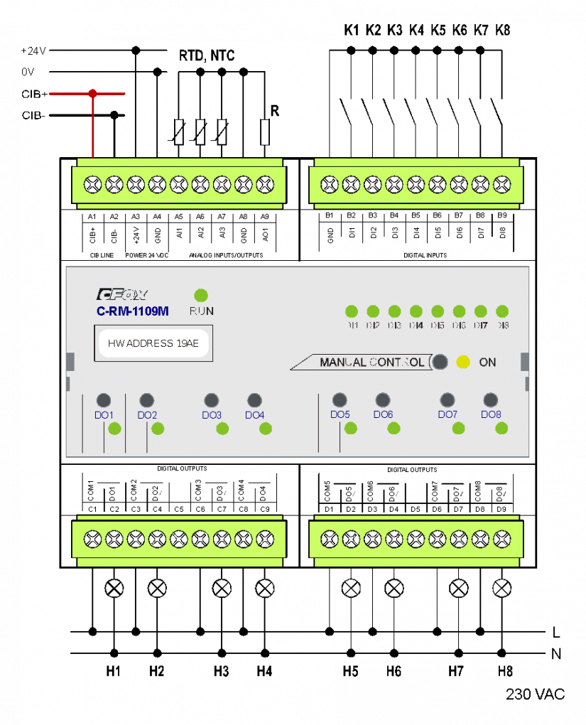
Fig. 1. An example of connecting the C-RM-1109M module.
Notes:
-
The GND and CIB- terminals are interconnected, see the internal wiring in Fig. 2.
The relay outputs of the C-RM-1109M module:
|
The DO1, a separate output, switching contact, continuous current in the output is 16 A, short-time overload 80 A (max. 20 ms) |
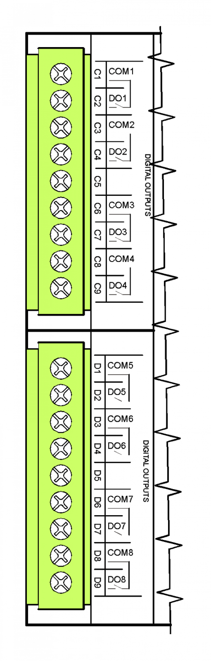 |
| There is only 1,750 VAC working isolation between these outputs. | |
|
The DO2, a separate output, switching contact, continuous current in the output is 10 A, short-time overload 50 A (max. 20 ms) |
|
|
isolation voltage from the other circuits and outputs is 3,750 VAC, i.e. safe isolation of circuits. |
|
|
The DO3, a separate output, switching contact, continuous current in the output is 16 A, short-time overload 80 A (max. 20 ms) |
|
| There is only 1,750 VAC working isolation between these outputs. | |
|
The DO4, a separate output, switching contact, continuous current in the output is 10 A, short-time overload 50 A (max. 20 ms) |
|
|
isolation voltage from the other circuits and outputs is 3,750 VAC, i.e. safe isolation of circuits. |
|
|
The DO5, a separate output, switching contact, continuous current in the output is 16 A, short-time overload 80 A (max. 20 ms) |
|
| There is only 1,750 VAC working isolation between these outputs. | |
|
The DO6, a separate output, switching contact continuous current in the output is 10 A, short-time overload 50 A (max. 20 ms) |
|
|
isolation voltage from the other circuits and outputs is 3,750 VAC, i.e. safe isolation of circuits. |
|
|
The DO7, a separate output, switching contact continuous current in the output is 16 A, short-time overload 80 A (max. 20 ms) |
|
| There is only 1,750 VAC working isolation between these outputs. | |
|
The DO8, a separate output, switching contact continuous current in the output is 10 A, short-time overload 50 A (max. 20 ms) |
|
|
isolation voltage from the other circuits and outputs is 3,750 VAC, i.e. safe isolation of circuits. |
The parameters of the connectors used are listed in Chap. 13.3.1
The module is in a 6M box.
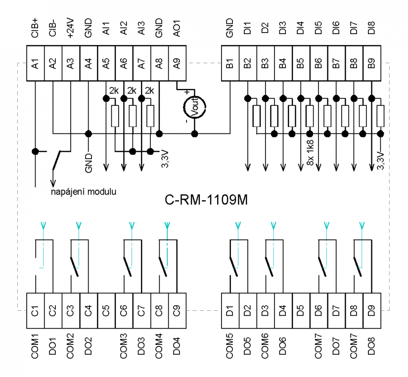
Fig. 2. Internal wiring of the C-RM-1109M module