
The module is designed to supply power for controlled heating and for the measurements of the precipitation detector S-RS-01I, also for heating and measurements of the 24 V rated voltage icing sensors (mainly products of the V-system company), see Chapters xxx, including switching the defrosting cables.It is also possible to connect 2 probes for level measurement to the module, e.g. for monitoring water level limits in the tank. The inputs and outputs can be used as general AI/DI and DO.
The module contains 5 analogue inputs, of which 3 are designated for connecting resistive sensors, or as standard digital inputs; 2 analogue inputs are designed for AC resistance measurement in sensors for icing, precipitation and point level probes.
Furthermore, the module is fitted with a PWM output DO4 intended for supplying and controlling heating of the sensors. The output is only intended to power these sensors with a power input about 2 W; the output circuits have no overload protection.
The C-IS-0504M module is also equipped with 3 relay outputs, 1 x 16 A and 2 x 5 A, e.g. for switching heating cables for defrosting, and the like.
Individual re lay outputs can be manually locally controlled via the buttons on the module panel.
The basic parameters of inputs and outputs:
|
The type of input (a connected sensor), the inputs AI1, AI2, AI3 |
The range of measured values |
|
Pt1,000 |
-90 °C ÷ +320 °C |
|
Ni1000 |
-60 °C ÷ +200 °C |
|
NTC 12k |
-40 °C ÷ +125 °C |
|
KTY81-121 |
-55 °C ÷ +125 °C |
|
Maximum resistance 100 kΩ |
0 ÷ 100 kΩ |
|
Voltage 2 V |
0 ÷ 2,100 mV |
|
The input resistance of inputs for voltage ranges. |
approx. 100 kΩ, see the Fig. internal wiring |
|
16-bit pulse counter (water meters, etc.) |
> 30 ms pulse, frequency max. 20 Hz |
|
The type of input (a connected sensor), the inputs AI4, AI5 |
The range of measured values |
|
resistance, AC measurement |
0 ÷ 1000 kΩ |
|
The input resistance of inputs for voltage ranges. |
approx. 100 kΩ, see the Fig. internal wiring |
|
The DO4 output |
|
|
Nominal output voltage UJM |
24 VDC |
|
Adjustable duty cycle of the PWM output |
0 ÷ 100 % |
|
Output current |
maximum 80 mA |
|
The PWM frequency |
100 Hz |
|
Short-circuit and overload protection |
No |
The relay outputs of the C-IS-0504M module:
The DO1, a separate output, switching contact,
continuous current in the output is 16 A, short-time overload 80 A (max. 20 ms), more detailed information on the relay contacts
isolation voltage from the other circuits and outputs is 3,750 VAC,
i.e. safe isolation of circuits.
The DO2, DO3, outputs with a common terminal, switching contact,
continuous switching current 5 A, more detailed information on the relay contacts
The parameters of the connectors used are listed in Chap. 13.3.1
The module is in a 3M box.
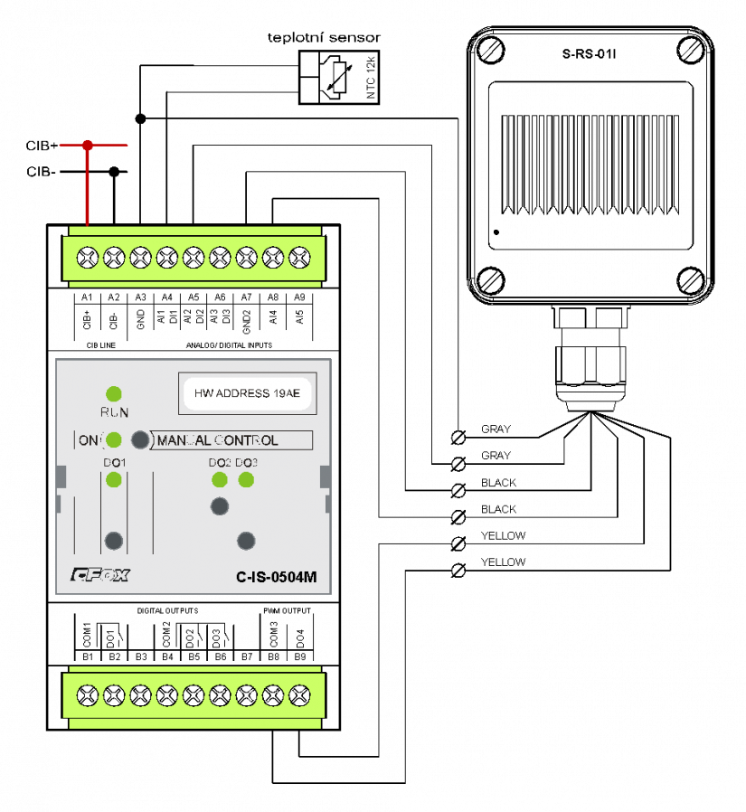
Fig. 1. Basic wiring of the C-IS-0504M module with the S-RS-01M precipitation detector
Notes:
-
The D04 output is designed solely for the heating of sensors with the power up to 2 W, 24 VDC.
-
The AI4 and AI5 inputs measure the resistance using AC voltage of approx. 3.3 V; the input is intended solely for the measurement of conductivity sensors and probes - it is not designed to measure temperature or other parameters.
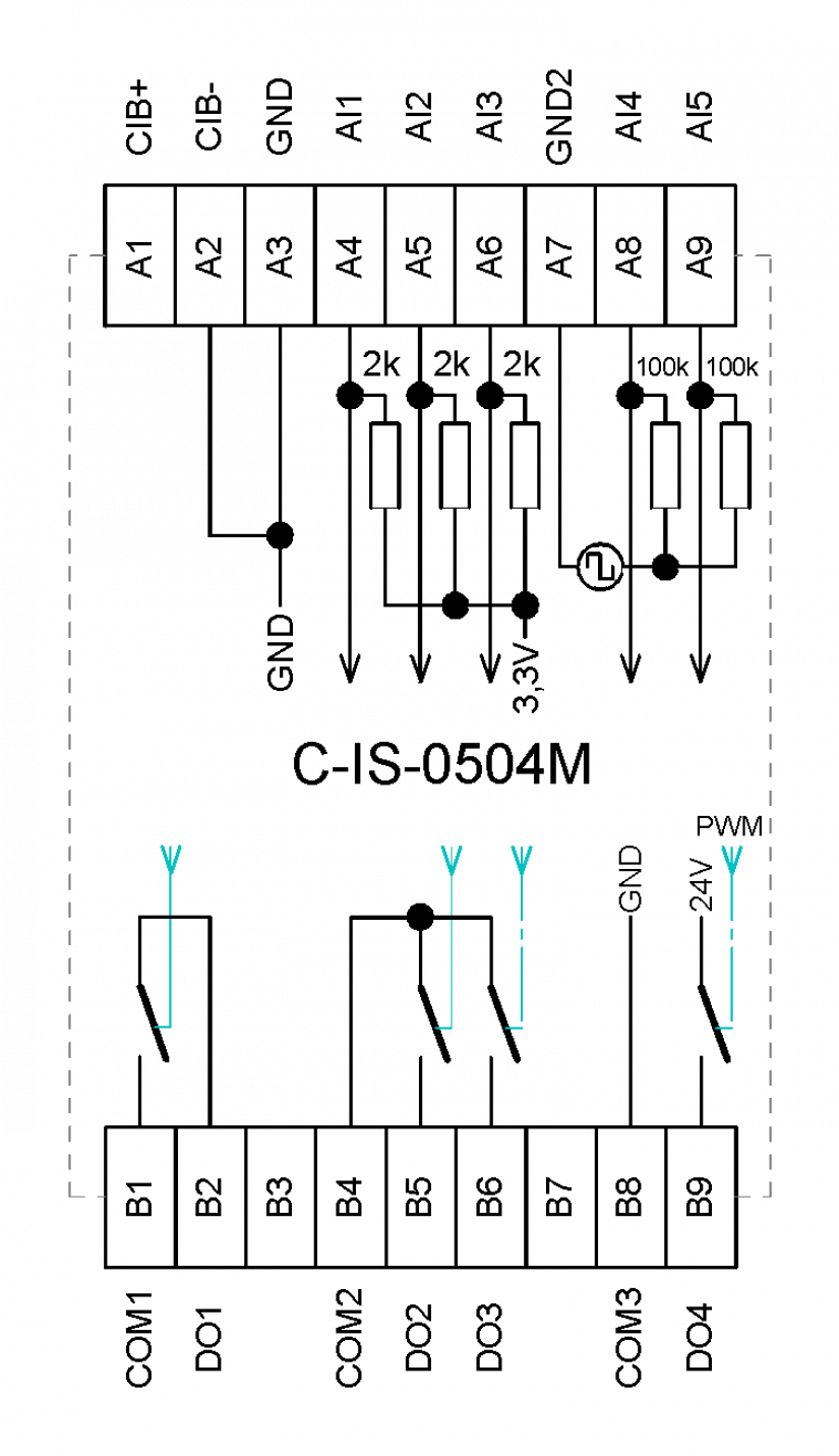
Fig. 2. Internal wiring of the C-IS-0504M module