
The C-IT-0504S module (order number.: TXN 133 26) is designed to connect analogue or digital signals and analogue outputs 0 - 10 V directly on the CIB bus. The inputs, outputs and the CIB bus should be connected to the module via a fixed terminal block.
The universal inputs can be set to binary or analogue in the SW configuration of the module in two groups. The first group contains 4 inputs, the second 1 input. The setup is common for the whole group. E.g. one temperature sensor (AI) and four input contacts (DI), or one input contact (DI) and four temperature sensors (AI).
The temperature measurements are made using the PT1000 and Ni1000 resistive sensors, and the NTC12k or KTY81-121 thermistor against the common GND wire. The resistance is converted in the module into a numerical value of temperature and transmitted to the central unit via the CIB bus. Other types of RTDs can use the resistance measurement range from 0 to 160 kΩ, but the conversion to temperature and the linearization must be done on the user programme level.
Binary signals are connected to the inputs only as free (dry) contacts against the common GND wire. The binary input can also operate in the mode of balanced input.
The analogue outputs voltage 0 ÷ 10 V is terminated on the terminals against the common GND wire.
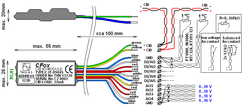
Fig. 1. The signal layout of the C-IT-00504S module, the wire colour coding and the basic connection
(the old version before November 2012)
Basic parameters of the DI/AI1 - DI/AI5 inputs.
|
The input type (connected sensor) |
The range of measured values |
|
PT1000 |
-90 °C ÷ +320 °C |
|
Ni1000 |
-60 °C ÷ +200 °C |
|
NTC 12k |
-40 °C ÷ +125 °C |
|
KTY81-121 |
-55 °C ÷ +125 °C |
|
Maximum resistance 160 kΩ |
0 ÷ 160 kΩ |
|
Binary input |
Log. 0 >1.5 kΩ / log 1 <0.5 kΩ |
|
The loop resistance 2x 1k1 |
Basic parameters of the analogue outputs AO1 ÷ AO4
|
Nominal output voltage UJM |
10 V |
|
Adjustable range of output voltage |
0 ÷ 130 % UJM |
|
Loading resistance |
>1 kΩ |
|
Maximum load capacity |
250 nF |
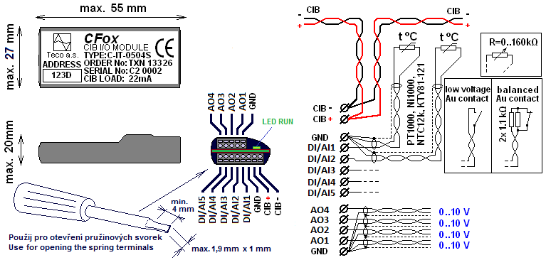
Fig. 2. The signal layout of the C-IT-0504S module, the wire colour coding and the basic connection
(the new version after November 2012)
Notes:
-
The inputs and outputs of the module are terminated in a miniature terminal block
-
The terminal block allows the release of the wire using a narrow screwdriver (see the figure), or even a common pin: insert it into the hole above the space for the wire and then pull the wire.
-
The LED is next to the terminal block and it is partly hidden under the housing of the module.
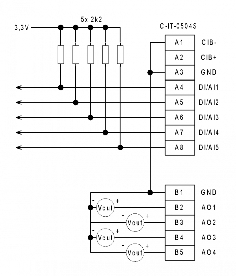
Fig. 3. Internal wiring of the C-IT-0504S module