
The C-IR-0203M is a module on the CIB bus, which comprises of two universal analogue or binary inputs, two relay outputs with a changeover contact (each is separately terminated) and one output
optionally adjustable as analogue, with the range from 0 to 10 V, or with a PWM output with adjustable amplitude and frequency.
The C-IR-0203M is implemented in a 1.5M box (dimensions 11/2 of a single-phase circuit breaker) on a DIN rail.
Basic parameters of the analogue inputs and outputs:
|
The type of input (connected sensor), inputs AI/DI1, AI/DI2 |
The range of measured values |
|
PT1000 |
-90 °C ÷ +320 °C |
|
Ni1000 |
-60 °C ÷ +200 °C |
|
NTC 12k |
-40 °C ÷ +125 °C |
|
KTY81-121 |
-55 °C ÷ +125 °C |
|
Maximum resistance 160 kΩ |
0 ÷ 160 kΩ |
|
Binary input |
Log. 0 >1.5 kΩ / log 1 <0.5 kΩ |
|
A balanced contact |
The loop resistance 2x 1k1 |
|
An analogue output AO1 |
Range 0÷ 10 V |
Range PWM |
|
Nominal output voltage UJM |
10 V |
- |
|
The output signal amplitude |
- |
10 ÷ 24 V |
|
Adjustable range of output voltage |
0 ÷ 130 % UJM |
- |
|
The frequency of PWM output |
- |
100 ÷ 2000 Hz |
|
Loading resistance |
>1 kΩ |
|
|
Maximum load capacity |
50 nF |
|
|
Galvanic isolation of the output from CIB |
No |
|
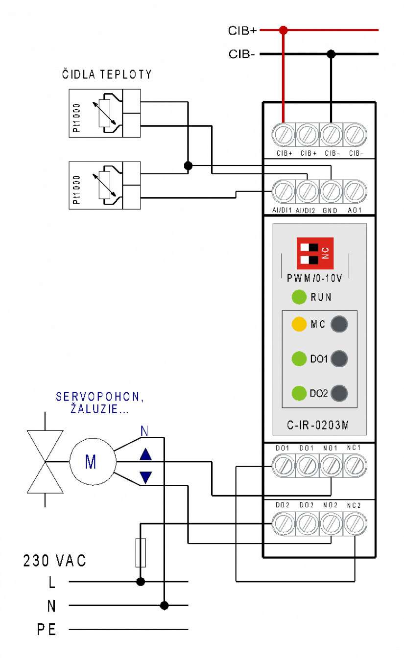
Fig. 1 An example of wiring the C-IR-0203M module.
Notes:
-
The relay outputs DO1 and DO2 are fitted with relays with changeover contacts 16 A.
-
The analogue output AO1 can be configured by a switch on the front panel either as a standard output 0 ÷ 10 V, or as an active output PWM with adjustable frequency 100 Hz to 2 kHz and with the amplitude 10 to 24 V.

Connecting the changeover contact of the relays on the module terminals.

Fig. 2 Internal wiring of the C-IR-0203M module
Notes:
-
The range AO1 (0 to 10 V or PWM) is set via the jumpers on the front panel and in the software configuration.