
The relay outputs are divided into two groups. The groups are separated from each other and from other circuits by isolation voltage of 3,750 VAC, so they meet the conditions of safe isolation of circuits.
It is possible e.g. to switch the 230 VAC circuits by the outputs DO1 to D03, and the circuits of safe low voltage can be switched by the DO4 to DO6 outputs.
Each relay output is designed for a maximum continuous current of 3 A (short current 5 A); a maximum current on the common terminal COM2, or COM3, is 10 A.
The relay contacts have a lifetime of approx. 100,000 operations under full load, and a maximum of 20 operations per minute. This must be taken into consideration when using relay outputs.
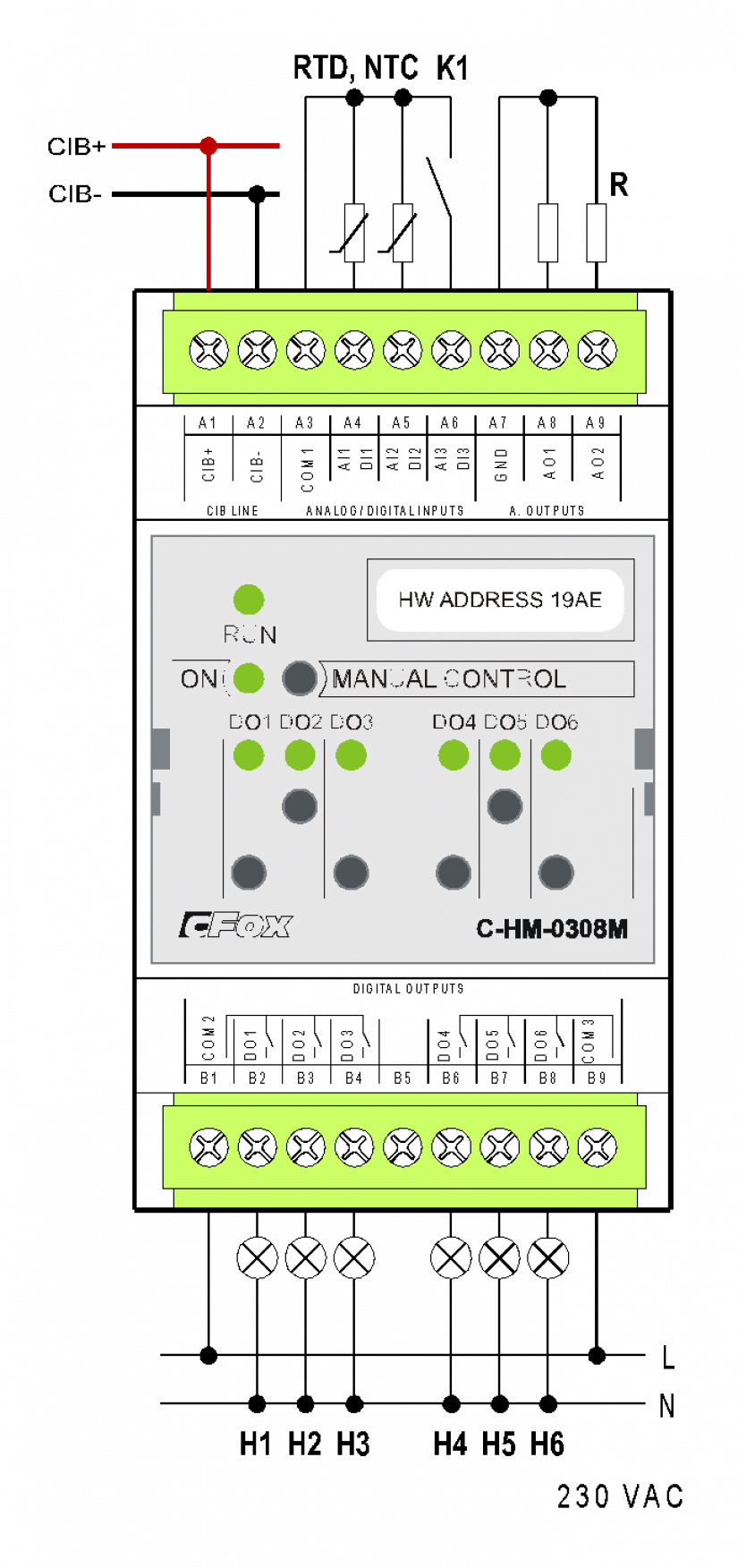
Fig. 1 The basic connection of the C-HM-0308M module
Notes:
-
The analogue inputs AI1 to AI3 are intended for connecting the temperature sensors and condensation sensors. The actual sensor should be connected between the input AI and the reference terminal COM1. The COM1 terminal has the +2.5 V reference voltage terminated (opposite the GND terminal).
-
The relay outputs are divided into two groups. Maximum currents and isolating voltages are listed in the following description.
The parameters of the connectors used are listed in Chap.13.3.1.
The module is in a 3M box on a DIN rail.
The basic parameters of inputs and outputs:
|
The type of input (a connected sensor), the inputs AI/DI1, AI/DI2, AI/DI3 |
The range of measured values |
|
PT1000 |
-90 °C ÷ +320 °C |
|
Ni1000 |
-60 °C ÷ +200 °C |
|
NTC 12k |
-40 °C ÷ +125 °C |
|
KTY81-121 |
-55 °C ÷ +125 °C |
|
Maximum resistance 600 kΩ |
0 ÷ 630 kΩ |
|
Maximum resistance 6 MΩ |
0 ÷ 6.5 MΩ |
|
Voltage 2 V |
0 ÷ 2.1 V |
|
Voltage 1 V |
0 ÷ 1.05 V |
|
Voltage 100 mV |
0 ÷ 105 mV |
|
Voltage 50 mV |
0 ÷ 52.5 mV |
|
The input resistance of inputs for voltage ranges. |
1 kΩ |
|
Binary input, the current in active input (switched contact) |
2.5 mA |
|
The analogue outputs AO1, AO2 |
|
|
Nominal output voltage UJM |
10 V |
|
Adjustable range of output voltage |
0 ÷ 105 % UJM |
|
Loading resistance |
>1 kΩ |
|
Maximum load capacity |
50 nF |
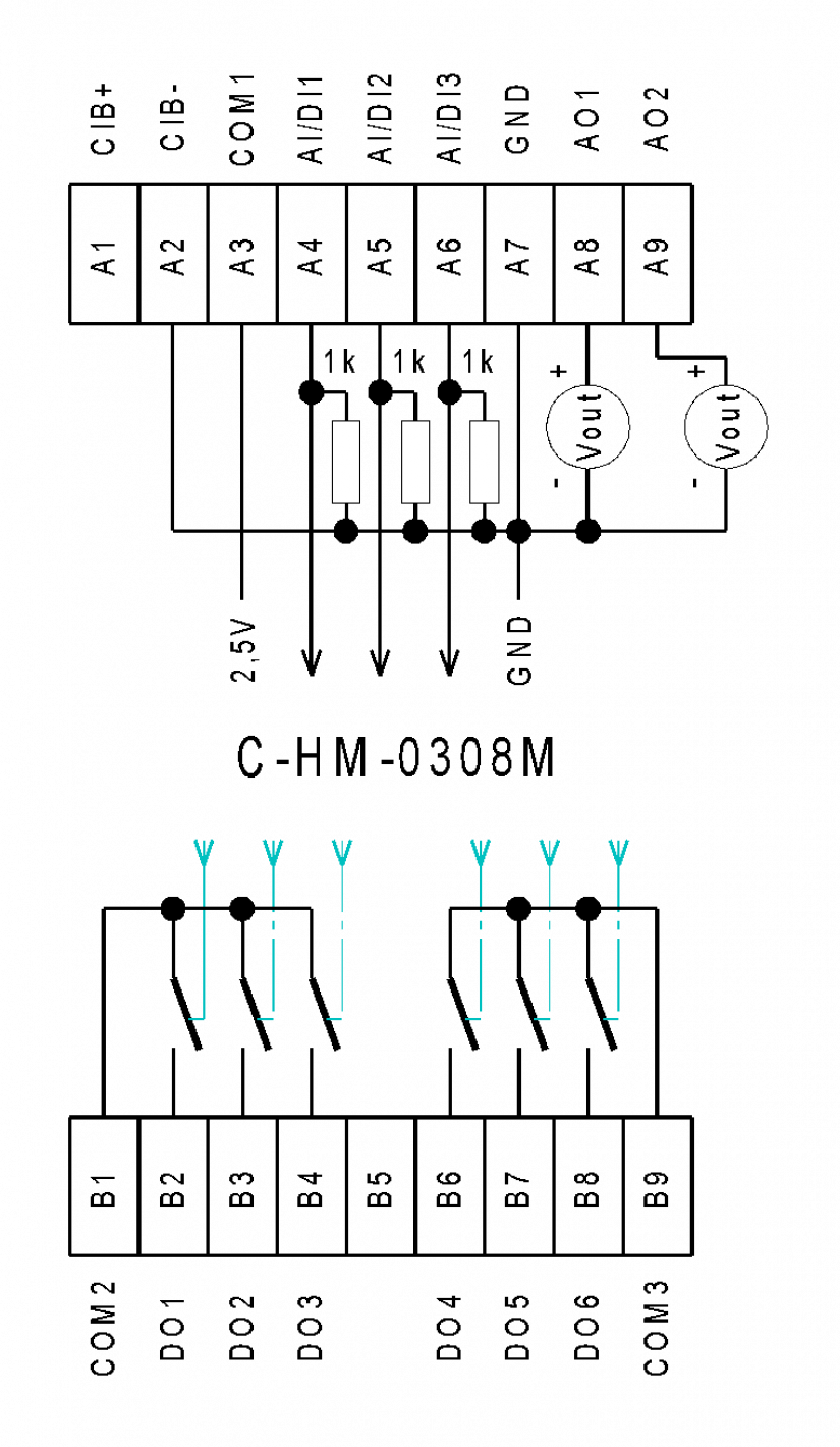
Fig. 2 Internal wiring of the C-HM-0308M module