
The device is designed for remote monitoring of energy consumption. It is designed for installation on a DIN rail. It is suitable for a wide range of applications in energy and so-called smart grids, in the automation of buildings and individual production processes, for remote monitoring of infrastructure and also for automatic load control. For connection to the control system, it is available in a version with a CIB bus (C-EM-0300M) or an RFox2 wireless connection (R-EM-0300M-A). The device measures three voltages and three currents.
- four-quadrant power measurement and electricity meter according to PPDS requirements
- extended, more accurate and continuous measurement of harmonic phasors (amplitudes and angles)
Connection and measurement
- AC power supply from measured voltages 115 ÷ 280 V
- three voltage inputs (L1, L2, L3) for direct or indirect voltage measurement in star connection, single-phase and Aaronic. Measurement category 300 V CAT III.
- 6.4 kHz sampling, continuous measurement
- calculation of 50 components of harmonic voltages and currents
- evaluation of all commonly measured single and three-phase quantities such as powers (active, reactive, apparent, deformation and fundamental active and reactive), power factors, harmonics and THD voltages and currents
- the device is realized for connection of current transformers with 333 mV output, information about selected types is here.
Technical parameters
| Auxiliary supply voltage | |
| nominal supply voltage range | 115 – 280 VAC
115 – 300 VDC |
| range e.g. voltage (AC), f: 40 ÷ 100 Hz | 100 – 310 VAC |
| supply voltage range (DC) | 100 – 330 VDC |
| power consumption | 7 VA / 2 W |
| overvoltage category | III (300 V) |
| degree of pollution | 2 |
| maximum altitude | 2000 m |
| connection | galvanically isolated, arbitrary polarity |
| Other parameters | |
| operating temperature | -25 ÷ 70 °C |
| storage temperature | -40 ÷ 80 °C |
| operating and storage humidity | < 95 % - without condensation |
| communication interface | CIB or RFox2 by variant |
| sampling frequency 50 Hz (60 Hz) | 6,4 kHz (5,76 kHz) |
| RTC accuracy | ± 2 seconds per day |
| RTC backup battery capacity | > 5 years (without connected supply voltage) |
| IP degree of protection front panel whole device |
IP 40 IP 20 |
| protection class | II |
| dimensions | 54 x 90 x 61 mm |
| weight | 0,13 kg |
Measured quantities
|
Measured quantities – voltage |
|
|
Frequency |
|
| fNOM – nominal | 50 / 60 Hz |
| measuring range | 40 ÷ 70 Hz |
| measurement uncertainty | ± 10 mHz |
|
Voltage |
|
| UNOM (UDIN) – specified voltage | 180 ÷ 250 VAC |
| swing factor at U NOM - nominal | 2 |
| measuring range (phase, UL-N) | 8 ÷ 355 VAC |
| measuring range (associated, UL-L ) | 14 ÷ 615 VAC |
|
measurement uncertainty (tA=23 ±2 ºC) |
+/- 0,05 % of value ± +/- 0,1 % of range |
| temperature drift | +/- 0,03 % of value ± +/- 0,01 % of range / 10 ºC |
| measurement category | 300 V CAT III |
| permanent overload | 1355 VAC (UL–N) |
| peak overload, 1 second | 2140 VAC (UL–N) |
| power consumption (impedance) | < 0.05 VA (Ri = 6.12 MΩ)) |
| Voltage asymmetry | |
| measuring range | 0 ÷ 10 % |
| measurement uncertainty | ± 0.5 |
|
THDU |
|
| measuring range | 0 ÷ 20 % |
| measurement uncertainty | ± 1 |
|
Harmonic to order 50 (40 @ 60 Hz) |
|
| reference conditions | other harmonics up to 200% class 3 according to IEC 61000-2-4 ed. 2 |
| measuring range | 10 ÷ 100 % class 3 according to IEC 61000-2-4 ed. 2 |
| measurement uncertainty | twice the class II levels according to IEC 61000-4-7 ed. 2 |
| Measured quantities - powers, power factor, energy | |
| Active / reactive power, power factor (PF), cos φ (PNOM = UNOM x INOM) | |
| reference conditions “A”: ambient temperature(tA) U, I for active v., PF, cos φ for reactive power |
23 ± 2 ºC U = 80 ÷ 120% UNOM, I = 1 ÷ 120% INOM PF = 1.00 PF = 0.00 |
| active / reactive uncertainty in. | ± 0.5% of value ± 0.01% PNOM |
| uncertainty PF, cos φ | ± 0.01 |
| reference conditions “B”: ambient temp. (tA) U, I for active p., PF, cos φ for reactive power |
23 ± 2 ºC U = 80 ÷ 120% UNOM, I = 2 ÷ 120% INOM PF >= 0.5 PF <= 0.87 |
| active / reactive uncertainty in. | ± 1% of value± 0.01% PNOM |
| uncertainty PF, cos φ | ± 0.01 |
| thermal drift performance | ± 0.05 % of value ± 0.02 % PNOM / 10 ºC |
| Energy | |
| measuring range | corresponds to measuring ranges U, I 4 counters corresponding to 4 quadrants for active and reactive energy separately |
| uncertainty of active energy measurement | class 1 according to EN 62053 – 21 |
| nejistota měření jalové energie | class 2 according to EN 62053 – 23 |
Table 2: IEC 61557-12: Equipment for measuring and monitoring electrical parameters
|
Device properties according to IEC 61557-12 |
|
| power quality | |
| device classification according to chap. 4.3
direct voltage connection PTN voltage connection |
SD SS |
| temperature class according to chap. 4.5.2.2 | K55 |
| humidity + altitude according to chap. 4.5.2.3 | < 95 % - without condensation < 2000 m |
| active power and active energy performance class | 1 |
|
Functional performance classes according to IEC 61557-12 Model „X/333mV“ with PTP „xxx/333mV“, INOM = xxx A, UNOM = 230 V |
||||
| Mark | Function | Třída | Measuring range | Note |
| P | total active power | 1 | 0 ÷ (993.6 * INOM) W | |
| QA, QV | total reactive power | 2 | 0 ÷ (993.6 * INOM) var | |
| SA, SV | total apparent power | 1 | 0 ÷ (993.6 * INOM) VA | |
| Ea | total active energy | 1 | 0 ÷ (993.6 * INOM) Wh | |
| ErA, ErV | total reactive energy | 2 | 0 ÷ (993.6 * INOM) varh | |
| EapA, EapV | total apparent energy | 1 | 0 ÷ (993.6 * INOM) Vah | |
| f | frequency | 0.02 | 40 ÷ 70 Hz | |
| I | phase current | 0.5 | 0.1 ÷ 1.2 * INOM ASTŘ | |
| IN | measured neutral current | – | – | |
| INc | calculated neutral current | 0.5 | 0.1 ÷ 1.2 * INOM ASTŘ | |
| ULN | phase voltage | 0.05 | 40 ÷ 280 VSTŘ | |
| ULL | combined voltage | 0.05 | 70 ÷ 480 VSTŘ | |
| PFA, PFV | power facotr | 0.5 | 0 ÷ 1 | |
| Pst, Plt | flicker | – | – | |
| Udip | short-term voltage drops | – | – | |
| Uswl | short-term voltage increases | – | – | |
| Utr | transient voltage | – | – | |
| Uint | interrupt voltage | – | – | |
| Unba | voltage asymmetry (amplitude) | 0.5 | 0 ÷ 10 % | |
| Unb | voltage asymmetry (phase and amplitude) | 0.5 | 0 ÷ 10 % | |
| Uh | voltage harmonics | 1 | do řádu 25 | 1) |
| THDu | total harmonic distortion of voltage (% U 1. harm) | 1 | 0 ÷ 20 % | 1) |
| THD-Ru | total harmonic distortion of voltage (% Ueff) | 1 | 0 ÷ 20 % | 1) |
| Ih | current harmonics | – | – | 1) |
| THDi | total harm. current distortion (% I 1. harm.) | 5 | 0 ÷ 200% | 1) |
| THD-Ri | total harmonic current distortion (% Ieff) | 5 | 0 ÷ 200% | 1) |
1) according to IEC 61000-4-7
Fig. 1 electricity meter connection C-EM-0300M
RF interface parameters of the R-EM-0300M module
are listed in the article Basic parameters of RFox2 modules
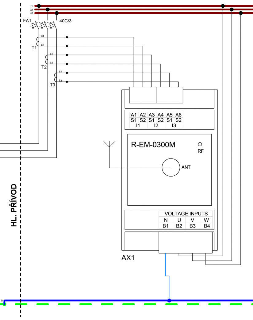
Fig. 2 electricity meter connection R-EM-0300M-A