
The basic module CP-2005 is the basic module of the Foxtrot 2 control system. It is in standard version on DIN rail, in 6M cover (for dimensions of box see chapter 13.2.2 6M mechanics on DIN rail), equipped with four removable terminal blocks. It is also equipped with two independent Ethernet interfaces, one USB device interface for connecting the master system and one USB host interface for connecting external memory (USB Flash Drive).
The basic module includes an integrated display of 4 x 20 characters and 7 buttons. In addition to system setup and diagnostics, the display and buttons can also be used in the user program.
The basic module also includes a slot for an additional micro SD card (not available in variants with a WLAN1 interface). Some variants of the basic module are equipped with internal WLAN1 interface for WiFi network or LTE1 for GSM network (see below).
The TCL2 system bus can be connected to the basic module for communication with the FOXTROT family peripheral modules and the CIB Common Installation Bus® (trademark of Teco a.s., hereinafter referred to as CIB) for communication with CFox family modules.
Optionally, the basic module can be fitted with two serial channel submodules.
The basic module CP-2005 can also be powered via the ETH1 interface using a so-called power injector. The 24 V supply voltage is routed through an Ethernet cable with two pairs of wires not used for signals (see Chapter XXXX).
The ETH2 interface can be used to power the connected ID-3x type operating panel (see Chapter XXX).
Basic module variants
The basic module CP-2005 is supplied in several variants distinguished by a combination of numbers and characters following the dot in the order number (eg TXN 120 05.11NSNN). In this way, a combination of different memory sizes for the DataBox, with optional WLAN1 and LTE1 interfaces, and a different integrated display size are defined. The principle of marking individual variants is given in Tab. .x1
Tab. 1 Designation of variations of basic module TECOMAT FOXTROT CP-2005.
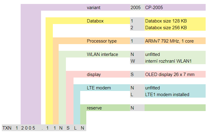
PNote: If WLAN1 is not installed, an internal micro SD card slot can be used.
If the WLAN1 is installed, the use of an additional micro SD card is not possible.
It is not possible to set up WLAN1 and LTE1, but only one of them.
All CP-2005 variants include an integrated 26 x 7 mm display.
As shown in Tab.1, the specific TXN 120 05.11NSLN represents the basic module CP-2005 with inputs and outputs in 6 DI / AI configuration, 6 DO, 2 AO, 128 KB dataBox memory, ARMv7 792 MHz single core processor, without the internal WLAN1 interface, the integrated display is 26 x 7 mm and the internal LTE1 interface is fitted.
Fitting I/O
Power supply 24 VDC, power consumption max. 10W (for power supply see chapter 2.2)
AI0/DI0 ÷ AI5/DI5 6 analog inputs, without galvanic isolation with optional DI function:
ranges: Ni1000, Pt1000, 2 kΩ, 200 kΩ, 0 ÷ 20 mA, 4 ÷ 20 mA, NTC, DI 24V
AO0 ÷ AO1 2 analog outputs, without galvanic isolation, range 0 ÷ 10 V
DO0 ÷ DO5 6 relay outputs, galvanically isolated from other circuits, 3 A per output
ETH1 Ethernet 10/100 Mbit (RJ-45 standard), galvanically isolated from other circuits, see chapter 2.4.1xx, including external power input
ETH2 Ethernet 10/100 Mbit (standard RJ-45 connector), galvanically isolated from other circuits, see chapter 2.4.1xx, including external power output (for external panels, etc.)
CH1. CH2 Submodule 1, serial channels according to mounted submodule, see chap. 2.3.1xx
CH3, CH4 Submodule 2, serial channels according to mounted submodule, see chap. 2.3.1xx
USB1 USB host interface with type A connector for external memory (flashdisk)
USB2 USB device interface with micro B connector for Mosaic development environment
Analog inputs AI0 ÷ AI5
| Voltage ranges | 0 ÷ 2 V
0 ÷ 10 V |
| Temperature sensor Pt100, W100=1,385 or 1,391 | -90 °C ÷ +400 °C |
| Temperature sensor Pt1000, W100=1,385or 1,391 | -90 °C ÷ +400 °C |
| Temperature sensor Ni1000, W100=1,500or 1,617 | -60 °C ÷ +200 °C |
| Temperature sensor NTC 5k, 10k, 12k, 15k, 20k | -40 °C ÷ +125 °C |
| Temperature sensor KTY81-121 | -55 °C ÷ +125 °C |
| Current ranges | 0 ÷ 20 mA
4 ÷ 20 mA |
| Resistance measurement (OV) | 0 ÷ 2 kΩ
0 ÷ 200 kΩ |
| Input resistance for voltage ranges | > 20 kΩ |
| Input resistance for current ranges | 100 Ω |
| Internal voltage for resistance sensors | 9,194 V |
| Channel transfer time | typ. 20 μs |
| Recovery time for each channel | typ. 400 μs |
|
Binary inputs |
|
| Input type | Typ1, with common minus terminal |
| Input voltage for log. 0 | max. +5 VDC |
| Input voltage for log. 1 | min. +15 VDC
typ. +24 DC max. +30 VDC |
| Input current at log. 1 | typ. 5 mA |
| Minimum pulse width (even for counter) | 500 μs |
| Max. counter frequency (DI3 ÷ DI5 inputs only) | 1 kHz |
Inputs DI0 ÷ DI5 enable function of short pulse capturing.
Inputs DI3 ÷ DI5 can also be used as inputs for counters. Even when used as counter inputs, inputs are simultaneously usable as ordinary binary
Analog outputs AO0, AO1
| Output range | 0 ÷ 10 V |
| Maximum output value | 105 % upper limit of output range |
| Maximum output current | 10 mA |
| Max. load capacity | 50 nF |
Relay outputs
DO0 ÷ DO2, common terminal outputs, continuous current output 3A, short-time 5A, maximum continuous current common terminal COM1 is 10A, podrobnější informace o kontaktech relé
the isolation voltage between the output groups and the other circuits is 3750 VAC, ie safe circuit separation
DO3 ÷ DO5, common terminal outputs, continuous current output 3A, short-time 5A, maximum continuous current common terminal COM2 is 10A, podrobnější informace o kontaktech relé
The principles of protection and use for capacitive and inductive loads can be found in the chapter 13.7.1 Ochrana výstupních prvků (relé,...).
Terminal Blocks of the basic module are connectors with a cage clamp with a pitch of 5.08 mm. More detailed terminal parameters are given in chapter 13.3.1 Konektory se šroubovými svorkami, rozteč 5,08mm, moduly na DIN lištu.
Fig. .1 Basic example of basic module CP-2005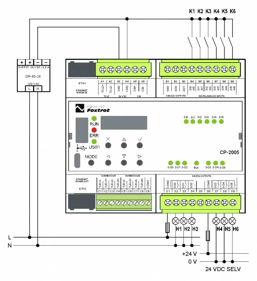
Wiring Notes:
-
The relay output groups (DO0 ÷ 2 and DO3 ÷ 5) can switch circuits powered from different sources. Groups are separated by isolation corresponding to safe circuit separation.
-
Optional AI input functions are set from the programming environment and jumpers placed under the removable cap above the respective connector, wiring examples are given in the following chapters.
-
The TCL2 bus is firmly terminated on the base module and must always be at the end of the bus line (see chapter 3.2).
-
module power supply, interface TCL2, CIB and CH1 have common signal ground, terminal GND (terminal A3). This terminal is connected to common AI / AO terminal (terminal B1).
-
Analog inputs AI0 ÷ AI5 are configured as inputs with a common negative terminal GND.
-
We recommend not to connect terminals A3 and B1 (GND) (they are connected by internal circuits). When powering CP and input circuits from one source (see example), we will not use terminal B1 at all. If we supply the circuits of the DI inputs from a separate source, then connect the negative terminal of this source to the B1 terminal.
The following figure 2 shows the connection of different analog sources and sensors and potential-free contacts:
input AI0 voltage - connect voltage eg 0 ÷ 10 V, positive terminal on AI0, negative terminal on GND,
input AI1 current, ie we connect a current source eg 4 ÷ 20 mA (powered loops must be provided by an external source, see example in chapter 11.3.9),
inputs AI2 , AI3 are passive - we connect two-wire resistance sensors (RTD) or resistance transmitters,
inputs AI4, AI5 are digital (ie evaluated as DI4 and DI5), standard 24V inputs with common GND terminal
inputs AO0, AO1 voltage outputs 0 ÷ 10V, connected load Rz (controlled circuits) in the picture.
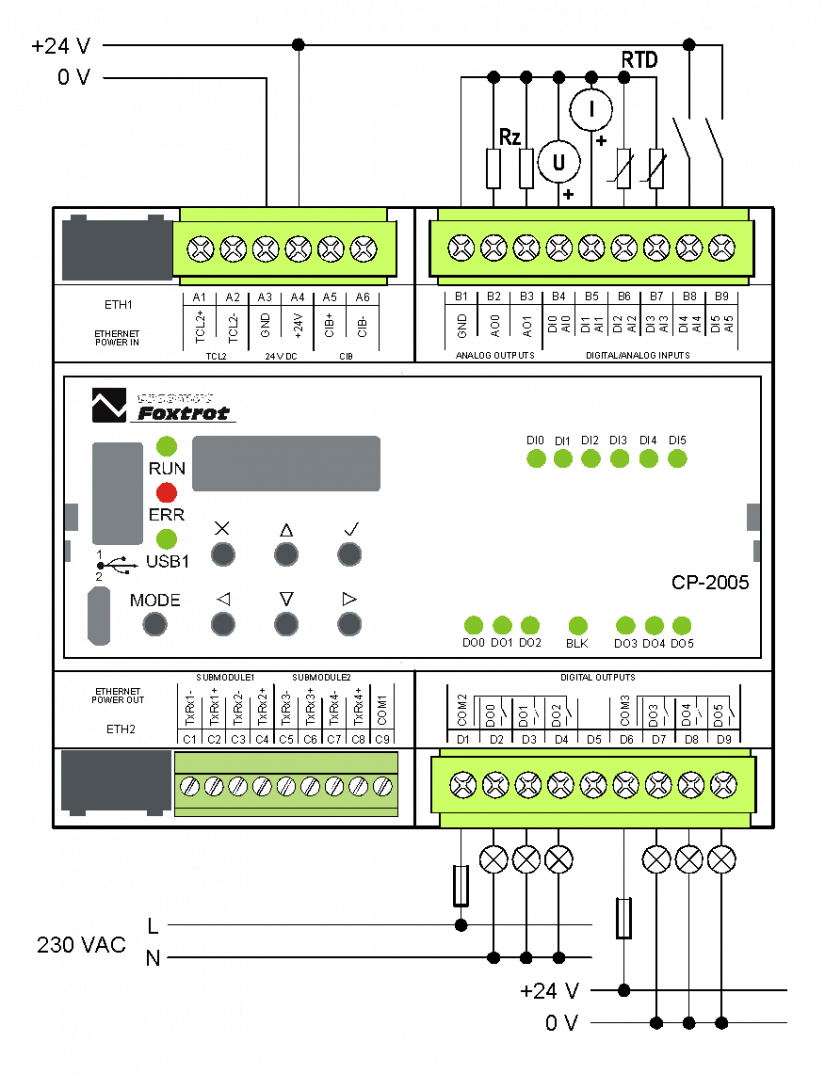
Fig. 2 Example of Analog Inputs and Output Connections in CP-2005 Basic Module