The module C-KY-0901R is controlled by 8 capacitive buttons (Fig. 1), for which short and long presses are detected. The long press delay is adjustable in the module initialization as well as the audible response to the press.
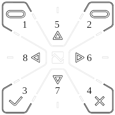
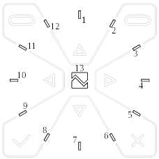
Fig. 1 Keyboard buttons Fig. 2 RGB LED signaling
The module contains 13 signaling RGB LEDs (Fig. 2), which can light up in 5 modes that define their behavior:
- 0 all off
- 1 bar graph - LEDs 1-13 light up gradually
- 2 flashing – the selected number of LEDs flashes periodically
- 3 rotation – 1 active LED rotating clockwise
- 4 logo - active logo (LED 13)
LED lights up in 7 predefined colors - see the color palette in Fig. 6.
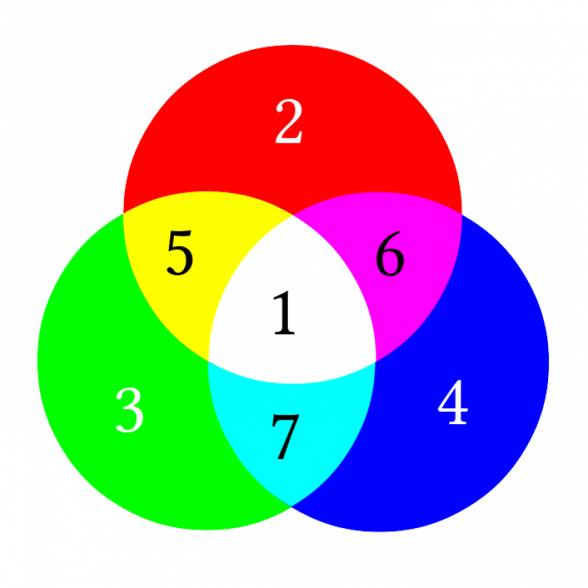
Fig. 3 Color palette
Configuration
The C-KY-0901R module is configured in the I / O Configurator (icon in the Tools menu). Activation of individual devices on the module is performed by selecting the appropriate device check mark.
The module is not supported in the older configuration tool, Project Manager !!!
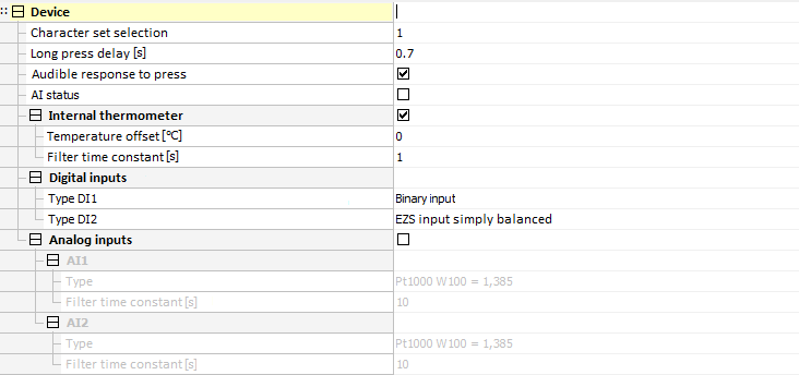
Fig. 4 Module configuration dialog in the I/O Configurator
Audible response to a press
Option to enable audible response at the touch of a button and RFID tag detection.
Long press delay
For buttons, the module directly evaluates short and long presses on individual inputs. By entering the value, you can set the time delay after which the activation of the binary input DI will be signaled as a long press (PRESS). Activation of a binary input shorter than this entered value will be signaled as a short press (CLICK). The delay value (Tpress) is entered in the range 0.1 ÷ 2.5s.

Fig. 5 Evaluation of short/long press
Temperature offset
Correction offset of the thermometer by which the measured temperature will be adjusted.
Temperature filtration
Entering a non-zero value for the time constant activates the 1st order digital filter. The filter is given by the relation
yt=yt−1+x+1
- x - current value of analog input
- yt - output
- yt-1 - past output
- ﺡ - first order filter time constant (TAU)
The value of the filtration time constant is entered in the range 1 ÷ 254 and represents the time constant in the range 1s ÷ 254s (the value 255 is intended for service purposes).
Module screen
The module display shows up to 8 icons (ICONS), one 16-digit (TEXT1) and two 8-digit texts (TEXT2 and TEXT3) centered.
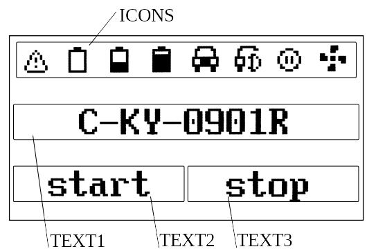
Fig. 6 Main screen
Structure of transmitted data
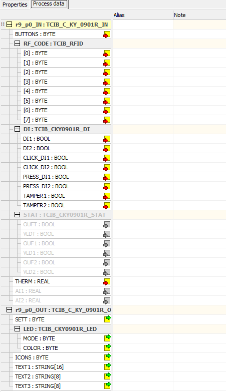
Fig.7 Structure of transmitted data for I / O Configurator
Input data
| BUTTONS | RF_CODE | DI | STAT | THERM | AI1 | AI2 |
BUTTONS - button press (byte type variable)
| - | CLICK | PRESS |
BUTT |
|||||
| Bit | .7 | .6 | .5 | .4 | .3 | .2 | .1 | .0 |
- BUTT - pressed button (1 - 8)
- PRESS - long press (to log. 1)
- CLICK - button press (to log. 1)
RF_CODE - RFID code (8*byte type variable)
DI - current status of binary inputs, short pulses, long pulses (6x bool type variable)
- DIx - current state on binary input x
- CLICK_x - short pulse (to log. 1) on binary input
- PRESS_x - long pulse (to log. 1) at the binary input
STAT - status byte of analog inputs (8x bool type variable)
| - | - | VLD2 | OUF2 | VLD1 | OUF1 | VLDT | OUFT | |
| Bit | .7 | .6 | .5 | .4 | .3 | .2 | .1 | .0 |
- STAT - status byte of analog inputs (8x bool type variable)
- THERM - internal thermometer value (real type variable) [°C]
- AI1 - analog input value 1 (real type variable) [°C],[kΩ],[mV]
- AI2 - analog input value 2 (real type variable) [°C],[kΩ],[mV]
Output data
| SETT | LED | ICONS | TEXT1 | TEXT2 | TEXT3 |
SETT - mobile settings (byte type variable)
| - | - |
KEYBOARD |
BUZZ | BACKL | ||||
| Bit | .7 | .6 | .5 | .4 | .3 | .2 | .1 | .0 |
- BACKL - turn on the display backlight
- BUZZ - turning on the audible alarm
- KEYBOARD - keyboard backlight intensity setting, 0 - 10 ie 0 - 100% in steps of 10%
LED - color LED settings
- MODE - bit 0-3 LED mode, bit 4-7 number of active LEDs (byte type variable)
- COLOR - LED color (byte type variable)
ICONS - icons(byte type variable)
TEXT1 - 1. line of text (16-digit)
TEXT2 - 2. line of text (8-digit)
TEXT3 - 2. line of text (8-digit)
