
Contents
Apendix A. Explanations and concepts
1. What is RF or radio signal
1.1 Introduction
RF or radio signal is an electromagnetic wave whose intensity decreases with the distance from the transmitter, therefore the range of the radio signal is limited.
The basic function of any wireless communication system is to transfer data from point A to point B. The longer the communication range, the more robust and efficient the system. Therefore, range is one of the most important parameters to consider when evaluating wireless RF networks.
IMPORTANT: Wired connections and wireless connections differ in one central point:
- Wired connections are static and do not change. Wireless connections, on the other hand, are dynamic. As external circumstances change, communication can change or be disrupted.
1.2 Understanding RF communication range
One of the most common questions developers often ask themselves during the network planning phase is “How long will my range be?” The answer seems simple – the RF module manufacturer should state the range that their modules provide. However, in many cases, the actual range in real-world conditions differs from the advertised range.
1.3 Radio waves and their propagation
In free space, radio waves propagate spherically. The signal strength decreases quadratically with distance. From a certain distance, the signal is so weak that it can no longer be received without errors or is attenuated by ambient noise.
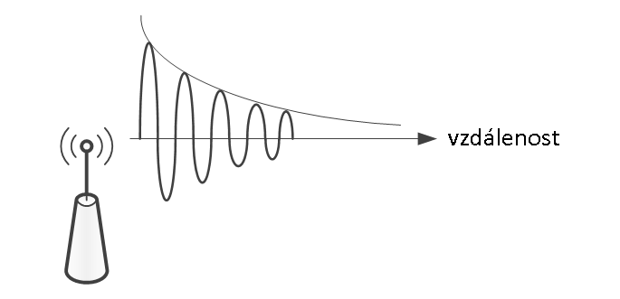
Fig 1. A demonstration of how signal strength decreases with distance.
1.4 Throughput
The range and propagation of a radio signal are affected by a number of other factors that must be taken into account.
For example, metal surfaces including metal reinforcements such as reinforcing mesh, traverses, metallized surfaces of insulating and thermal insulation foils, glass surfaces (windows, shop windows), etc.
All of these surfaces reflect radio signals to a greater or lesser extent, creating an electromagnetic shadow behind them.
A radio signal passes through ordinary masonry, but compared to a signal that propagates in open space, such waves are weakened by passing through an obstacle.
Some materials will attenuate the signal less, some more.
Tab. 1 RF signal transmission through various building materials
|
Material |
Signal transmission in % |
|
Brick walls |
60 - 90 |
|
Wood and drywall |
70 - 90 |
|
Reinforced concrete structures |
10 - 90 |
|
Metal partitions, aluminum thermal insulation |
0 - 15 |
|
Glass without glue and metal |
85 - 95 |
IMPORTANT: Before installation, it is necessary to measure the RSSI signal quality between the individual elements and the RF master. This procedure is often underestimated, but is an important first step in the installation.
IMPORTANT: As a rule, if the signal quality falls below (-96 dBm), the element must be relocated to maintain 100% functionality.
1.5 Reflections
Factors affecting radio waves
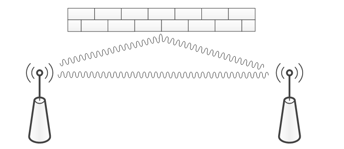
Fig. 2 Radio wave reflections
Radio wave reflections can have advantages as well as disadvantages:
- In rooms, reflections often have advantages because they allow you to reach every corner of the room, even if there is no direct line of sight between the transmitter and receiver.
- However, reflections can also cause interference
1.6 RF signal propagation
Narrow spaces with thick walls are not favorable for RF signal propagation because they shorten the range and signal quality.
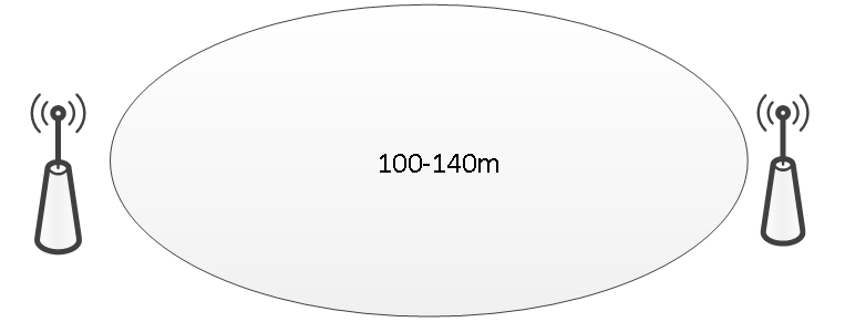
Fig. 3a An ellipsoid characterizes the propagation of an RF signal in open space
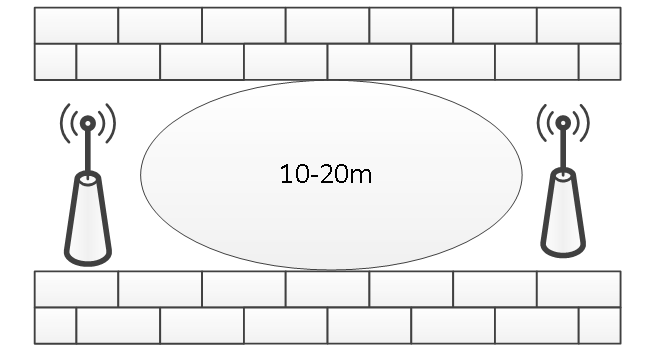
Fig. 3b The ellipsoid characterizes the propagation of an RF signal in a narrow room.
CONCLUSION: The pictures show a significant reduction in range.
The range of the RF signal is also determined by the type and construction of the building in which the RFox network is operated.
Generally, with visual contact, the range is typically up to 30 m in corridors, and up to 100 m in larger halls.
A successful indoor installation can be achieved by following the following recommendations:
Tab. 2 Typically, range and building conditions when managing antenna positions
|
Range |
Conditions |
|
Within 30 meters |
wide rooms without obstacles, mirrors and metal decorations |
|
Within 20 meters |
in a building with a lot of furniture and moving people with obstacles up to five walls (drywall etc.), two brick or concrete walls |
|
Within 10 meters |
When installed in a corner of a wall, the transmitter or receiver antenna is attached to a metal surface, or is affected by a narrow space |
|
Within 5 meters |
in case of spreading over 1-2 reinforced concrete ceilings In this case, the range is greatly influenced by the density and orientation of the reinforcements |
1.7 Distances from potential sources of interference
We recommend a minimum distance of 2m from potential sources of electromagnetic interference (e.g. Wi-Fi/LTE routers, weather stations, various wireless sensors of security systems, etc.)
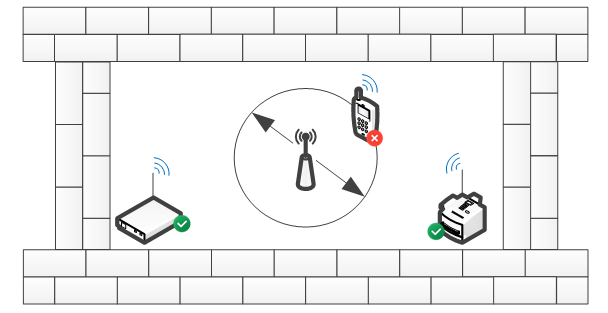
Fig. 4 Positioning of modules relative to other sources of interference.
1.8 Shielding
Various large objects that contain a large proportion of metal, such as:
Building reinforcements and beams, steel shells and walls of industrial halls or metal-plated parts of the structure, thermal insulation foils or air conditioning pipes, etc. that are hidden in building structures, create an electromagnetic shadow because they reflect electromagnetic waves similar to a mirror reflecting light.
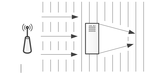
Fig. 5 How metal objects create an electromagnetic shadow
Various dividing walls prevent the direct propagation of the RF signal, as they do not transmit it, but reflect it. Nevertheless, the signal from a room with metal or reinforced concrete dividing walls gets out, using various construction or technological openings (windows, doors, etc.), which do not prevent the passage of electromagnetic waves or prevent it significantly less. However, such a signal is strongly attenuated and is mainly directional, i.e. it is sufficient (usable) only in a narrow sector given by the opening through which it spreads out.
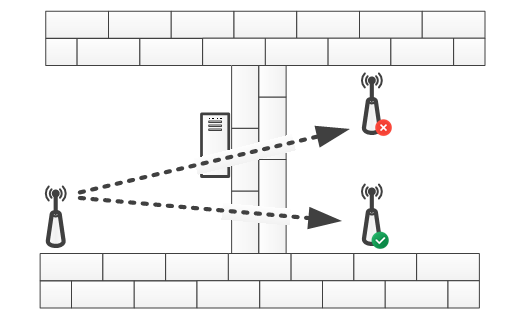
Fig. 6 Radio signal shielding in buildings
1.9 Transmission angle
The angle at which the RF signal passes through the wall is very important, as the signal attenuation varies depending on this angle. The signal must pass through the wall as directly as possible, taking the shortest path possible.
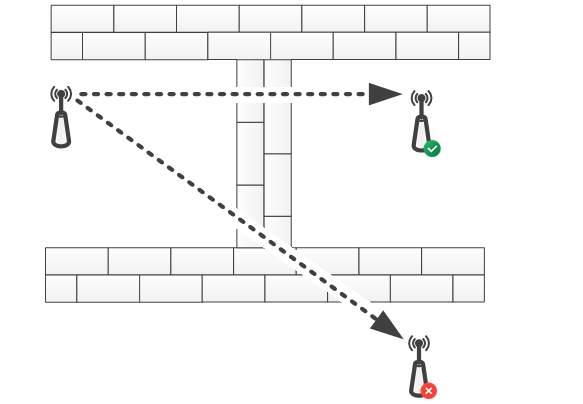
Fig. 7 Penetration of a radio signal through a wall at different angles
1.10 Antenna installation
The most important components of a wireless connection are the transmitting and receiving antennas and the method of their installation.
Therefore, antenna setup and placement is very important, as very small changes can greatly benefit a wireless connection.
It is important to follow the rules for the distance of the antenna from the ceiling, floor and walls, as they are the main factors that affect the range of wireless transmission.
External antennas usually have higher gain than integrated antennas hidden in a wireless device.
People or other objects that accidentally or permanently stand in the way of the radio signal also create an obstacle and reduce the overall range, which is why all Teco wireless modules that are installed in a built-up area usually have a range of up to 20m (up to 100m in open space).
Installing modules with built-in antenna
The module with a built-in antenna must not be installed on the same wall as the RF master or another module that serves as a router. If another location cannot be chosen, we must take into account that the radio signal propagates along the wall with difficulty and may be attenuated or completely scattered.
IMPORTANT: Installing an antenna or a device with an integrated antenna on or near a metal surface or near electrical cables or metal pipes can cause a loss of range of up to 30%.
It has been proven in practice that better results can be achieved by placing the modules on the side or opposite wall.
IMPORTANT: The internal antenna radiates minimal energy in the lateral direction.
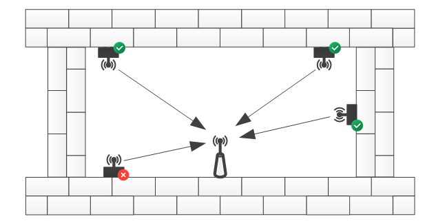
Fig. 8 Positioning of modules relative to RF master or router
Installing an external (magnetic) antenna
If the module has an SMA connector for connecting an external antenna, it is ideal to install this antenna in the middle of the room. Where possible, the external antenna should be installed at least 10 - 15 cm from the corner of the wall or concrete ceiling.
Attention: If the module is placed in a metal cabinet, it is necessary to use an external antenna.
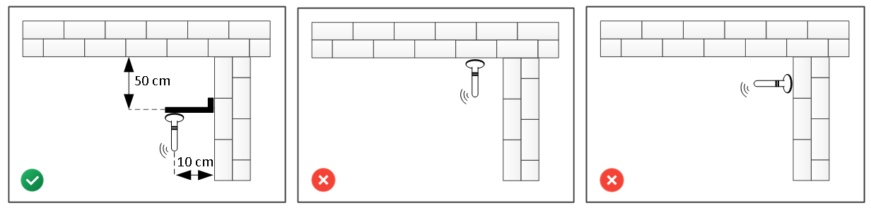
Fig. 9 Recommended method of installing an external antenna
2. Basic concepts of the RFox2 network
2.1 Introduction
RFox II (Radio Foxtrot) is a wireless radio bus. It operates in the license-free 868 MHz radio band and no additional permission is required for its operation.
Tab. 3. Basic parameters of the RFox II bus
|
Frequency band |
868.35 MHz (license free ISM band) CEPT ERC/REC 70-03 General License |
|
RF modulation type |
2-GFSK |
|
Communication type |
bidirectional (with packet acknowledgement) |
|
Transmission speed |
50 kbps |
|
Range |
100m line of sight, 25m built-up area |
|
RFox2 wireless network range |
256 RFox2 subordinate elements |
|
Communication frequency band/Transmission frequency |
868.1 MHz |
Communication takes place via an external RF master.
List of supported RF masters
- SC-1111-A (Single-channel external RFoxII modem/network master RFox II on the TCL2 system bus)
- C-RF-0001M-A. (Single-channel external RFoxII network master on the CIB system bus)
- RF-2131-A (Single-channel external RFoxII network master RFox II on the TCL2 system bus)
Important: RF-2131-A is only supported by Tecomat Foxtrot 2 PLC
2.2 RF Master
RF master is a communication module that extends the PLC with the ability to receive and send RF packets. Several masters can be used, the RFox2Lib library then automatically selects the most suitable master for communication with RF modules based on the signal strength. Thanks to the connection via the TCL2 or CIB line, individual masters can be located quite far from each other (see example 1).
2.3 Router
If it is not possible to communicate with the relevant RF module directly (it is too far from the RF masters or is shielded by an obstacle), we can use another RF module as a router. This router then forwards control packets from the PLC to the relevant RF module and status packets from the RF module to the PLC. Communication can also take place via several routers, if necessary.
Important: In the RFox II network, any module that is permanently powered can serve as a router.
2.4 RF Modem/master
When we need to connect two or more PLCs to transfer information and/or commands, we need to use an RF modem. The RF modem provides RF master functions for communicating with peripheral modules and simultaneously exchanging data between several PLCs.
2.5 RF address
In the RFox II network, each module has its own unique address. The address consists of two parts, the upper part contains the module type designation and the lower part contains the module serial (manufacturing) number.
This also applies to the central PLC module (master). If we want the PLC address not to depend on specific HW (e.g. when multiple PLCs communicate with each other), we can set a so-called user address, which is then carried with the program and remains the same when the PLC is replaced.
2.6 Network encryption key
Radio communication in the RFox II network is secured by a cipher that uses keys of 128 bits. By default, all modules use a common encryption key to understand each other. The user application has the option to set a user encryption key that differs from the default key and will be used preferentially. The RFox II network master automatically synchronizes the user encryption key to all its assigned RF modules. The RF modules then encrypt status data with this key and accept control data only if it is encrypted with this user key. This ensures that another central module that does not know the respective user encryption key does not understand status data from the respective RF modules, nor can it send control data to these modules. The RF modules remember the user encryption key even after power is disconnected.
In order to be able to use the RF module, e.g. in another application without prior knowledge of its encryption key, it is possible to delete the user key set in the RF module either using the button on the module or by a command from the master module to set a new key, which must arrive within a few minutes of turning on the power to the relevant module.
2.7 Signal strength (RSSI)
For RF devices, it is good to know the quality of the connection between two modules. One of the quality indicators can be the signal strength, which is usually abbreviated as RSSI (received signal strength indicator). This value is given on a logarithmic scale, the unit is dBm. The smaller the number, the weaker the received signal. Here, it is roughly true that around -40dBm is a very strong signal, up to about -80dBm is a decent signal and somewhere above -105dBm is the sensitivity limit of RF modules.
Because other modules can also transmit in the same band or interfere with it with electromagnetic emissions, e.g. switched power supplies (PC, TV, LED bulbs, dimmers, etc.), adding up all these sources of electromagnetic radiation creates the so-called background noise - it is actually the strength of the received signal if no module from our network is transmitting. For reliable RF communication, the signal from our RF modules at the receiver location must be stronger than the background noise.
The signal strength is greatly influenced by the location of the modules themselves. The signal is attenuated by obstacles made of solid material, such as walls, but the worst are obstacles containing metal - e.g. reinforced concrete ceilings, steel window frames, glass with wire filling, but also e.g. mirrors. At the same time, there is also reflection from the walls, so sometimes the signal reaches places that are shielded by such reflection - in a room with thick walls, for example, it passes through the door after several reflections from the walls of the corridor. Such communication can be reliable, but if someone is standing in the corridor, the communication may not work at that moment.
Therefore, it is crucial for the reliable function of the RF network to choose the correct location of the antenna from the master (PLC) so that the signal is not shielded by metal obstacles if possible. It is also advantageous to place it roughly in the middle of the area where the RF modules will be installed.
The signal strength (and thus the range) is also greatly influenced by the correctly chosen antenna. Our network will have a significantly greater range if, instead of a small baton antenna, we use (at least for the master) a larger one, for example a magnetic antenna, which has better radiation efficiency during transmission and greater gain during reception. The connecting cable between the antenna and the RF module should not be unnecessarily long, because it attenuates the signal and thus decreases the strength of the received signal.
If we want to cover a larger area, we can use multiple RF modems in different locations. The RF master can use multiple modems simultaneously and automatically selects the most suitable modem for communication with a specific module based on the signal strength.
3. Principle of RF communications
3.1 Introduction
Communication between the RF master and the RF module is supported for star and routing network topologies.
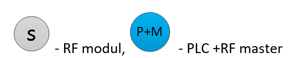
3.2 Star network
The star topology represents a direct communication range between the master and the RF module, the master always has a direct communication range with all slave RF modules.
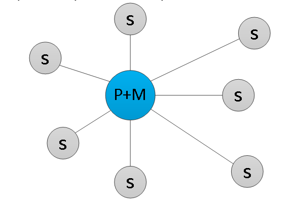
Fig. 10 Star topology example
3.3 Routing network
The routing network topology represents a distribution of served modules where the RF master has a direct communication range only with some modules, reaching other modules using so-called routers. A router (repeater) is a device that receives, amplifies and forwards the incoming RF packet. Using routers, the basic communication range of the master module can be increased.
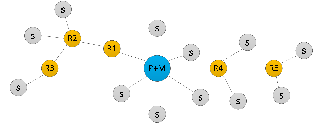
Fig. 11 Example of a routing network topology

A maximum of 10 routers can be used in one routing network. A sent RF packet must reach its recipient using a maximum of 11 hops. Each hop represents an increase in the time delay between sending and receiving an RF packet (the reaction time between command and action is extended). Either a dedicated RF router or any RF module in continuous operation can be used for the router function (the router function is assigned to the modules when configuring the modules in the RFox network).
In terms of operation, there can be modules with continuous operation and modules with intermittent operation in the RFox network. Modules with continuous operation are able to respond to RF master commands at any time (mostly permanently powered modules). Modules with intermittent operation go into “sleep“ mode, during which they do not respond to master commands (mostly battery-powered modules). Modules can go out of sleep mode based on a user action (e.g. pressing a button on the module), or based on a time action (timeout).
3.4 RF signal routing (repeating)
The scope of the system's usability is almost unlimited thanks to the routing technology. Communication is not limited by the normal range of radio transmission, because the elements of the RF system transmit information to each other even over greater distances if necessary. Transmission of the signal to the respective module is enabled by the nearest adjacent modules, using the routing/repeat function.
During commissioning and routing setup, the best quality connection must always be sought and the optimal communication path must be found.
When to use routing/repeat functions?
If the module has a weak signal range (below -96 dbm), but the installation does not allow the element to be moved, we can use the routing function through a module that shows a better signal level. This module/router receives the signal, amplifies it and sends it on. Thanks to this, we can also control an element that had a signal strength below -96 dbm during the first measurement without a router. We recommend a maximum of 2 routers in the electrical installation due to delay. We always place the router as close as possible to the obstacle, so that it is visible from both sides (transmitter and receiver) and the signal can bypass the impassable obstacle.
Even the router can have problems with signal transmission between floors (which are mostly made of reinforced concrete and therefore become impenetrable to RF signals). The solution is to use multiple RF masters in the installation connected by a CIB or TCL bus cable.
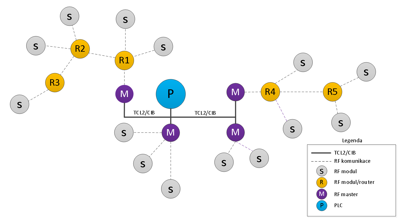
Fig. 12 Example of a routing network topology with multiple RF masters
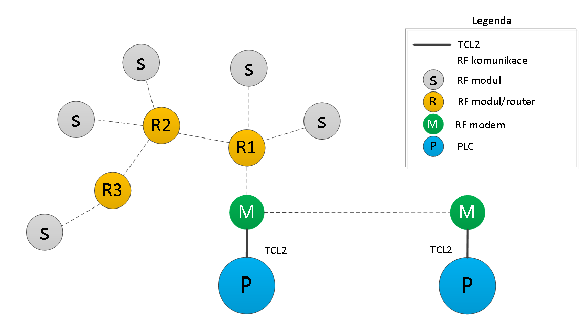
Fig. 13 An example of a routing network type topology with more PLCs
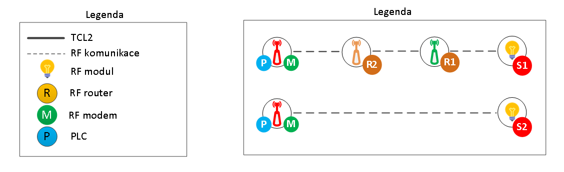
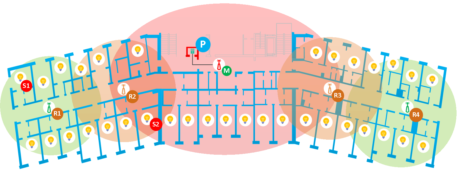
Fig. 14 Example of RFox2 network layout in a one-story guesthouse
Explanations and concepts
Hop - one hop of a routing packet
RF - radiofrequency
dBm: We often encounter this unit in power calculations. It is used to quantify power relative to 1 mW. For example, 0 dBm would mean 1 mW. Taking this as a reference, any increase on the mW side also translates into an increase on the dBm side. However, this increase on the dBm side is logarithmic. Which means at 10mW it's also 10dBm, but 100mW is 20dBm and 1000mW is 30dBm. Each multiplication of 10 in mW is simply an addition of 10 in dBm. Below is a table with some commonly used values.
Tab. mW to dBm conversion table
|
Power (mW) |
Power (dBm) |
|
0.001 mW |
-30 dBm |
|
0.01 mW |
-20 dBm |
|
0.1 mW |
-10 dBm |
|
1 mW |
0 dBm |
|
10 mW |
10 dBm |
|
100 mW |
20 dBm |
|
1000 mW |
30 dBm |
Interference: Interference or RF noise refers to all other signals available in the spectrum. Noise has many types and causes. It can be thermal noise from hardware components in everything from the RF modules themselves to nearby electrical appliances. Noise can also be caused by proximity to a transmitter on a different frequency.
Range: It refers to the minimum distance at which the transmitter and receiver can be placed while maintaining adequate signal levels.