A common task is the replacement of original Foxtrot CP-10xx series central units with the current Foxtrot CP-20xx models. Particularly with older projects, it is necessary not only to change the hardware configuration itself, but also to modify the project so that it uses the IO Configurator tool instead of the original configuration in the project manager under the HW Configuration node. In IO Configurator, the original central unit can then be replaced with a new one.
Converting a Project to IO Configurator
An automated tool assists with the conversion. The tool is launched from the Project / Copy project with conversion of configuration to I/O Configurator tool... . The original project is preserved in the project group.
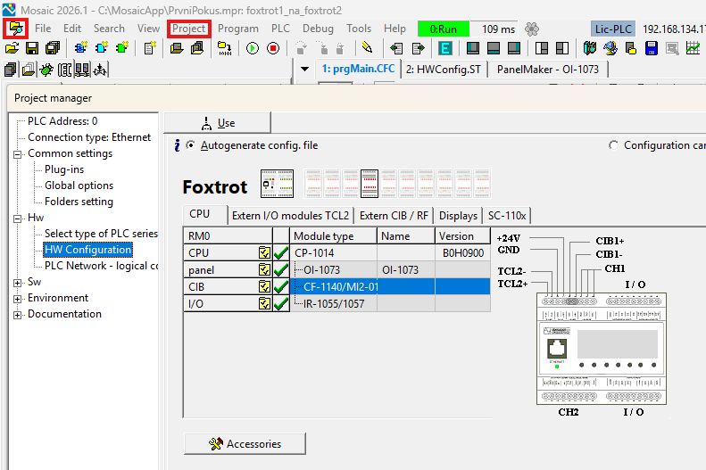
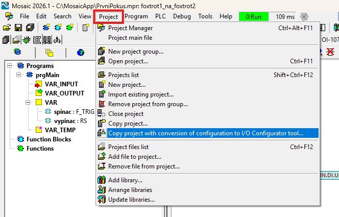
The new project name is derived from the original name by adding “..._IoCfg” to the end. The conversion process is logged, and the user can check for any errors and take action if the conversion cannot be performed automatically. A complete conversion cannot be performed, for example, for projects that include modules from the original RFox wireless system, which are no longer supported in IO Configurator; however, these are usually rare exceptions. The conversion report can be found in a file in the IOConfigurator folder within the new project, even after the tool window has been closed.
Replacing a CP-10xx Central Unit with a CP-20xx Series Unit
If the original CP-10xx series central unit has been configured using the IO Configurator, you can replace it with a new model via a local menu that opens when you right-click the central unit’s name.
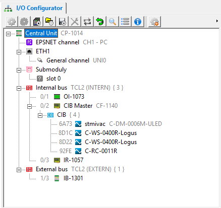
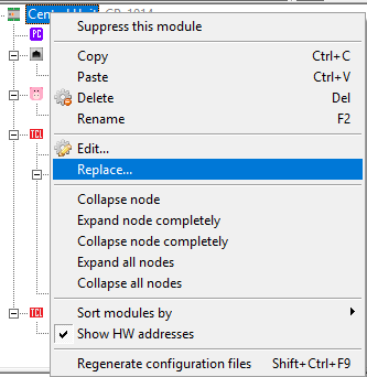
We'll start the replacement by selecting a new central unit.
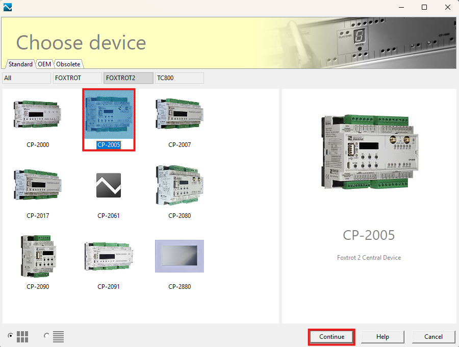
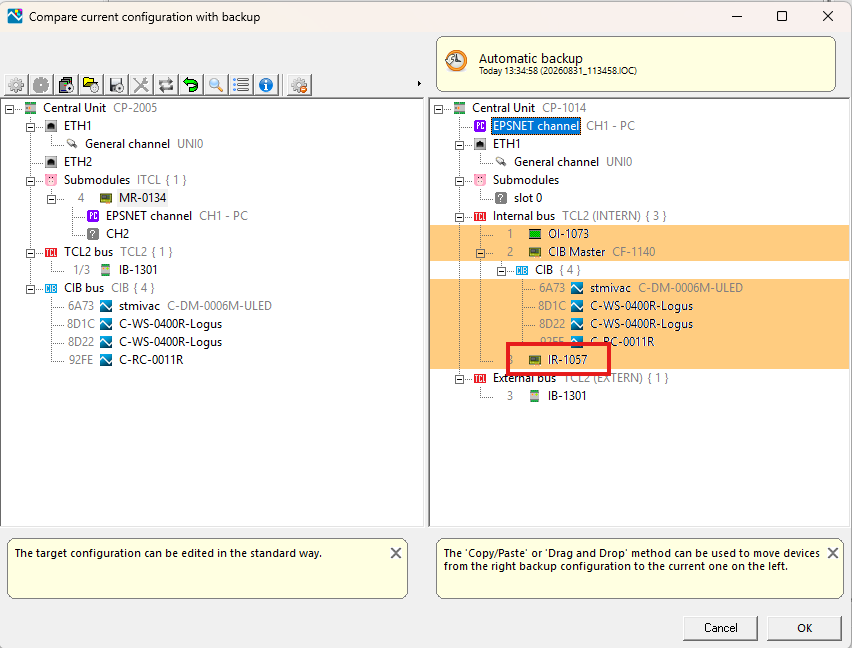
Since the first and second generation control units of the Foxtrot system are not 100 percent identical—even though the model designations suggest a direct succession (CP-1000 => CP-2000, CP-1005 => CP-2005), the Mosaic environment usually informs us that the conversion could not be completed automatically and displays a window for comparing the previous configuration with the new one. The window highlights in color the interfaces and modules that were not transferred and which need to be completed by hand.
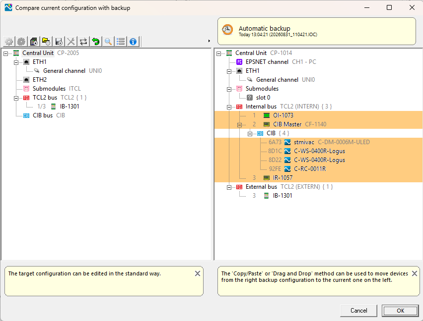
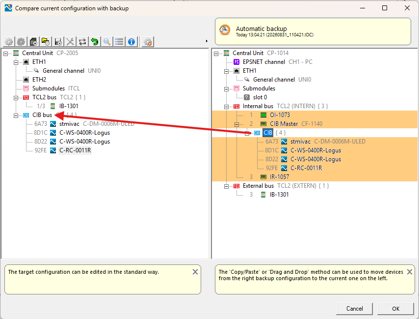
The comparison shows that the peripheral modules on the TCL2 bus (IB-1301) and the uni channels (in this case one) on the ETH1 interface were automatically transferred. The modules on the CIB, as well as the inputs and outputs on the central unit’s internal I/O module, were not transferred. The new system lacks the internal CIB master (CF-1140), but the entire bus branch can be clicked and dragged with the mouse from the right panel to the left by selecting the CIB section on the right panel and dropping it onto the CIB interface in the left panel. All modules will be transferred at once, including the symbolic names of their inputs and outputs and their configured properties.
If an interface is missing from the new system—such as the RS-232 interface in our example—you can easily add it in the left panel via the context menu. Since the CP-2007 does not have a built-in RS-232 interface by default, we will add it using an optional submodule. Right-click on the Submodules section and select the appropriate interface from the menu.
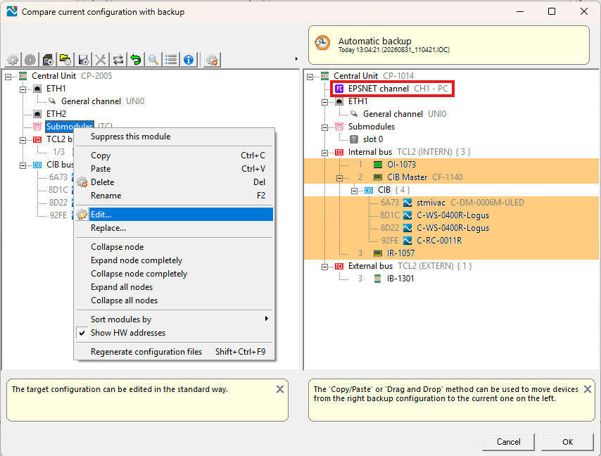
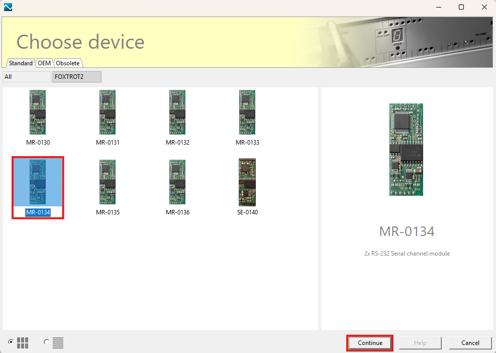
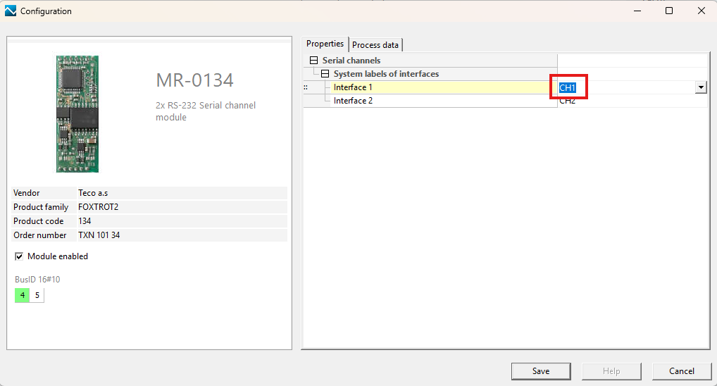
Once the interface has been added, we can move the channel in PC mode back from the right panel to the left. One advantage is that the Foxtrot 2 series systems allow us to number interfaces as we see fit, so we can assign the new interface the same designation it had in the original system. This way, we can avoid having to modify the user program (Note: In this example, the channel designation will be CH1, but this may not always be the case).
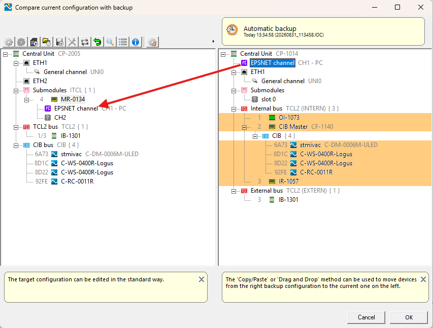
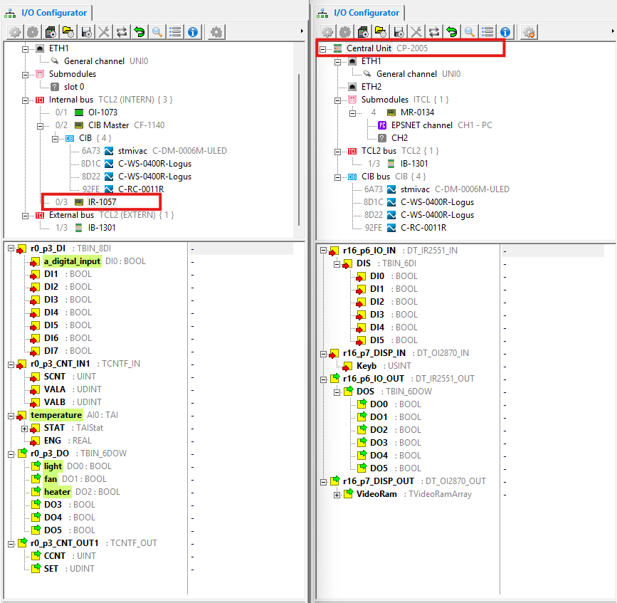
To complete the replacement, all that remains is to configure the inputs and outputs of the central unit itself. Here you may notice that for the CP-10xx series, the internal I/O module is listed separately in the overview so that the display matches the layout of the units according to the original configuration tool, but for the new CP-20xx series, the inputs and outputs are grouped under the central unit and configured within its settings.
Therefore, the signal descriptions and property settings for individual inputs and outputs will not be transferred, even if the number and type of inputs and outputs on the old and new units match. This is essentially the only part of the configuration that you’ll need to recreate. Probably the easiest way is to open both projects—the old one and the new one—in two separate instances of the Mosaic environment side by side and rewrite the user-defined names of the inputs and outputs.
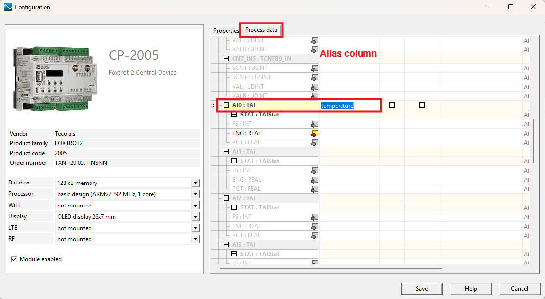
You can change the names of inputs and outputs either directly in the IO Configurator window (F2 key – Rename) or by double-clicking a signal to open the Configuration window, where you can enter the names of all signals at once in the Alias column on the Process Data tab. On the adjacent Properties tab, you can first enable and configure the parameters of the inputs or outputs if the signal is not active by default (see the documentation for the relevant central unit).
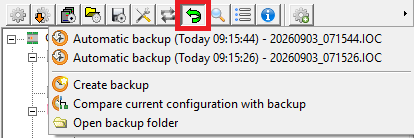
This completes the replacement of the central units. In case you need to revert to the original configuration or want to start the replacement process over, the configuration is automatically saved before the replacement begins, and you can return to the beginning at any time by clicking the Back icon on the IO Configurator toolbar.