
The IT-7602 module is designed for measurement and processing of signals from max. 16 analog sensors. Each module input can be set-up individually. The module ensures processing of the measured value to be used further in the user program (conversion to engineering units, etc.).

Figure 4.5.4.1 IT-7602 module connectors
General principles for sensor connection are described in chapter 4.2.2. At the same time, also principles of installation described in chapter 4.3 apply for the TC700 analog modules.
4.5.4.1 IT-7602 module connection examples
Example 1 The following signals are connected to the IT-7602 module:
- 2 signals 0÷10 V
- 2 signals 4÷20 mA
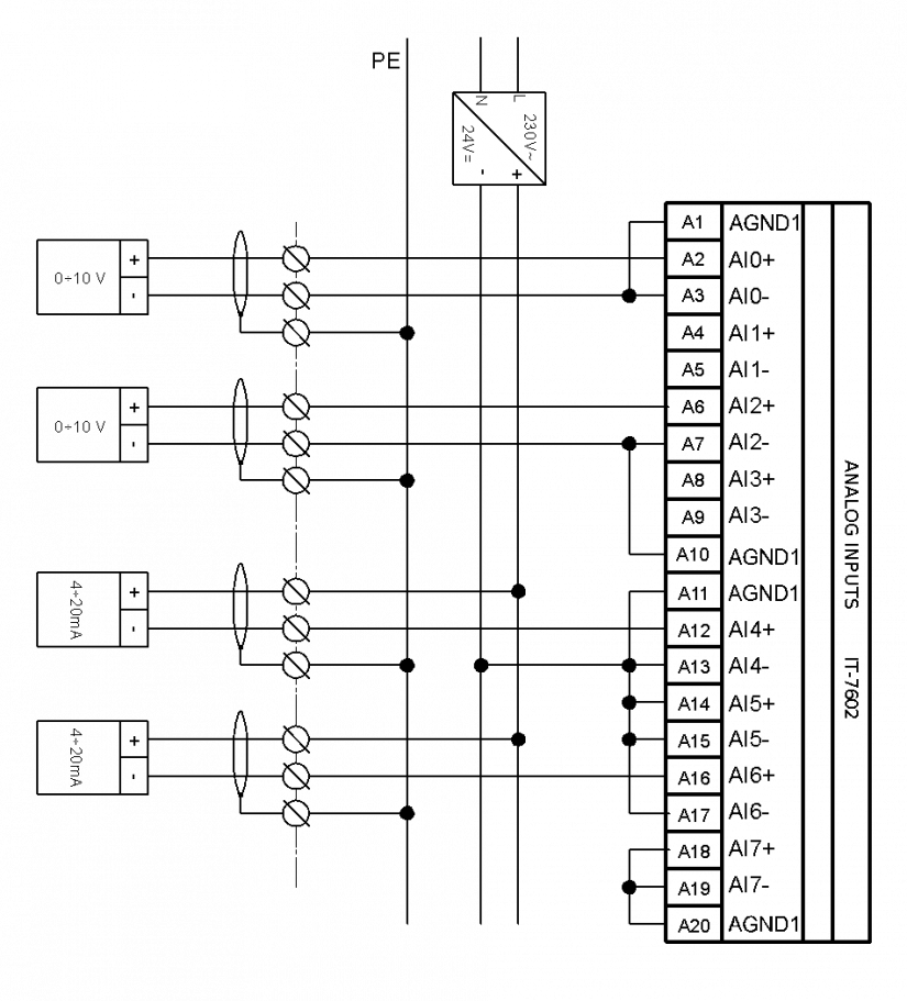
Figure 4.5.4.2 Connection of A connector of the IT-7602 module according to example 1
Notes:
-
Cable shielding is usually connected to the terminal of the working ground (on the unit or in the switchgear on the terminal board).
-
Current loops are fed by an external source, more current loops can be connected parallel to the source (see the IT-12 unit, example 1).
-
For small voltage signals, a shielded infeed conductor should be fitted (JYTY, etc.), shielding of which is connected according to general rules (see chapter 4.2.5).
-
Identical connection also applies to the B connector (second half of the module).