
The IT-7601 analog input module has 8 differential analog inputs used for standard signal measurement (10 V, 20 mA etc.). The module is galvanically isolated (all inputs together) from the other PLC circuits. Each input is program-adjustable independently of the other inputs.

Figure 4.5.2.1 IT-7601 module connectors
General principles for sensor connection are described in chapter 4.2.2. At the same time, also principles of installation described in chapter 4.3 apply for the TC700 analog modules.
4.5.2.1 IT-7601 module connection examples
Example 1 The following signals are connected to the IT-7601 module:
- 2 signals against ground 0÷10 V
- 2 signals against ground 4÷20 mA
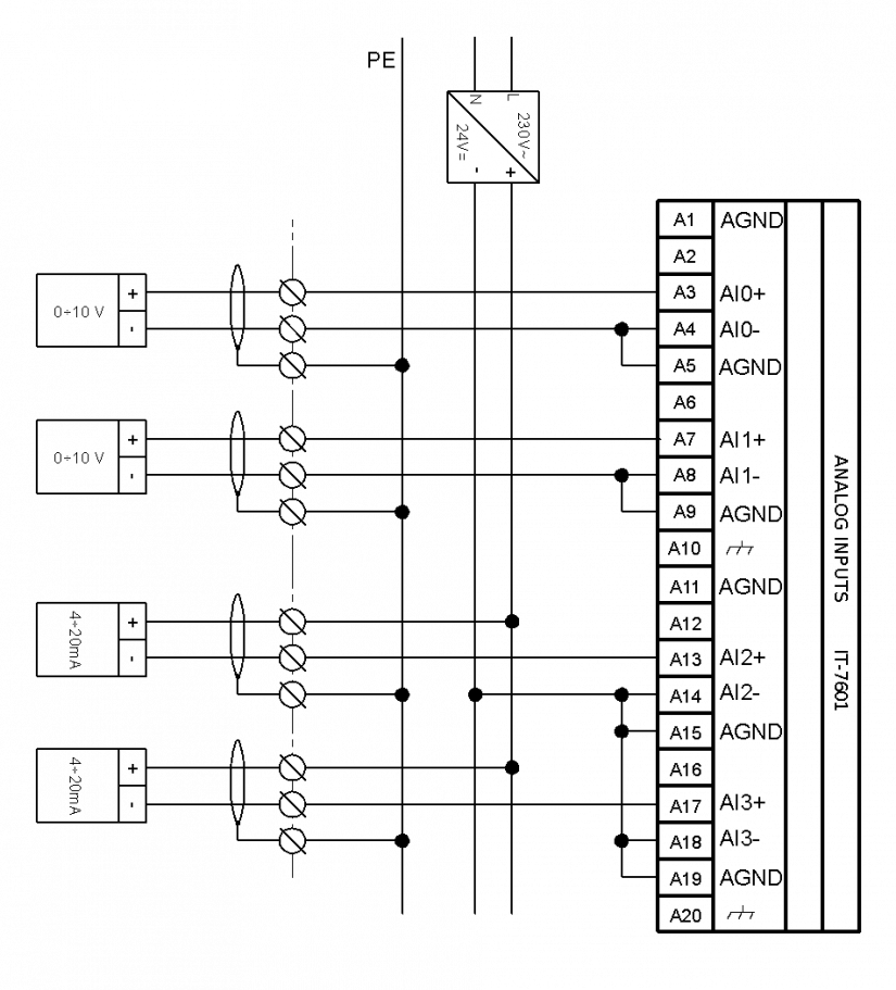
Figure 4.5.2.2 Connection of A connector of the IT-7601 module according to example 1
Notes:
-
When measuring voltage or current (differential measurement of the signal floating source), we always connect one input of each of such used channel (usually IN-) to the terminal of the analog ground of the AGND unit (a short-circuiting conductor or a resistor of up to 2kW can be used).
-
Cable shielding is usually connected to the terminal of the working ground (on the unit or in the switchgear on the terminal board).
-
When performing differential measurement of voltage or current, we always connect one input (IN-) to the AGND terminal!
-
Current loops are fed by an external source, more current loops can be connected parallel to the source (see the IT-12 unit, example 1).
-
For small voltage signals, a shielded infeed conductor should be fitted (JYTY, etc.), shielding of which is connected according to general rules (see chapter 4.2.5).
-
Identical connection also applies to the B connector (second half of the module).