

ID-74, order number TXN 055 22, is a 7-inch color graphic control panel with a touchscreen. It is designed to work with the TECOMAT TC800 and Foxtrot systems to display user made web pages. User screens are created in the Mosaic programming environment using the WebMaker tool and are identical to the pages available in Tecomat via the web server viewed through a web browser.
The panel features a backlit 7-inch capacitive touchscreen TFT LCD display with a 16:9 aspect ratio and a resolution of 1024x600 pixels. Power is supplied by an external 24 V DC power supply. Communication between the control system and the ID-74 panel takes place via a 100Base-TX Ethernet interface. the panel is designed for wall mounting in a standard 68 mm installation box, or for mounting on a control panel door using a panel mounting bracket (TXN 055 22.91) and double-sided adhesive film (TXN 055 22.92), which must be ordered separately.
Order numbers for the ID-74 and optional accessories:
TXN 055 22 Complete ID-74 operator panel kit for installation in a junction box (consists of the panel, base, and mounting screws).
TXN 055 22.91 panel mounting bracket for 7" (bracket for mounting the complete ID-74 panel into an opening in an enclosure, e.g., a control cabinet)
TXN 055 22.92 Double-sided adhesive sticker for 7" (adhesive sticker for attaching the ID-74 panel to an opening in an enclosure, e.g., a control cabinet)
TXN 055 22.95 7" wall-mount bracket (bracket for mounting the ID-74 panel on a drywall)
Panel Mounting
The Panel module can be mounted on a thin panel, such as a sheet metal or plastic cabinet door. For installation, you can order a double-sided adhesive pad and a snap-on mounting bracket with M4 screws, which are used to secure the module from the back of the panel. If the panel is very thin, you can use different, longer M4 screws.
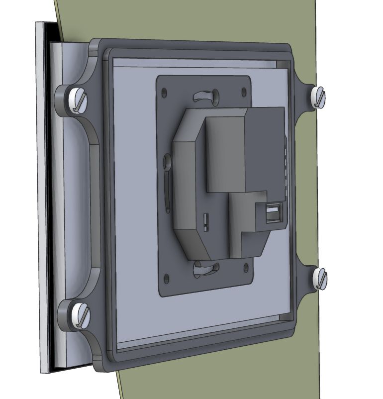
Fig. 1 Installation of the ID-74 on a thin wall
The hole in the wall must be cut out with considerable precision, because the self-adhesive film (shown in black in the figure) is thin. Figure 2 shows the required dimensions of the hole and the placement of the ID-74 panel relative to the hole.

Fig. 2 Dimensions of the mounting hole for the ID-74 in a thin wall
The placement of the self-adhesive film (highlighted in blue) is shown in Fig. 3. The mounting screws on the snap-on bracket are visible on the sides.
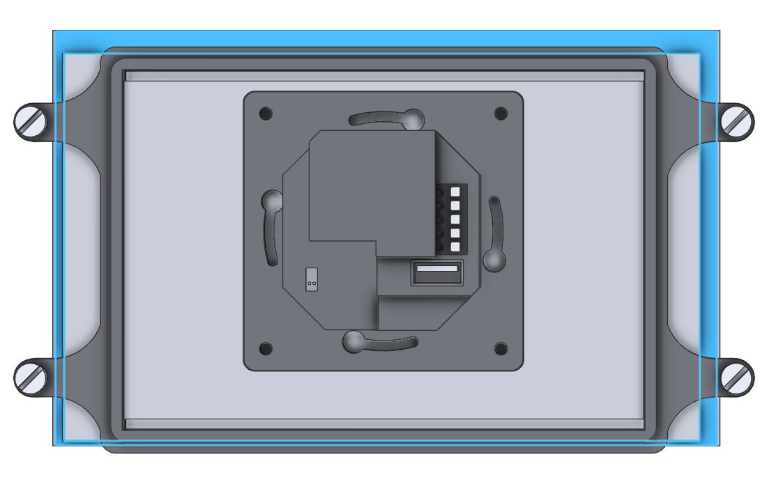
Fig. 3: Placement of the self-adhesive film and mounting bracket (the double-sided adhesive sticker is shown in blue)
Mounting on a brick wall
The ID-74 Panel is primarily designed for wall mounting on a standard junction box, such as the KU-68. The base, which includes an Ethernet connector and 24 V power terminals, is screwed onto the installation box. The panel itself—its main component—is then snapped onto the secured base. This completes the installation.
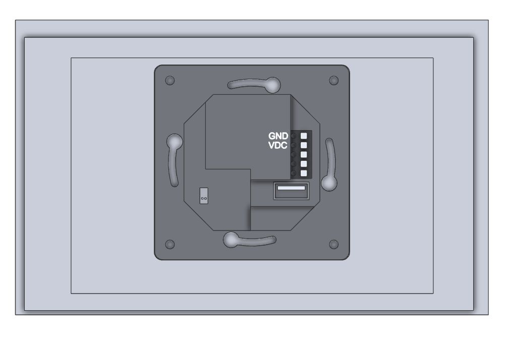
Fig. 4: Rear view of the ID-74 in a configuration for mounting on a junction box
Notes:
- The base, which is screwed onto the junction box, is shown in dark gray
- Ensure correct orientation during installation as shown in the figure (Ethernet connector facing down)
- The base features a terminal block to which the 24 VDC power supply is connected; the terminals are labeled in the figure (negative terminal GND, positive terminal VDC)
- The panel itself hooks onto the top of the base (be careful of the interconnecting connector), then is tilted down and snapped into place using the lower tabs.
- To remove the panel, follow the steps in reverse—pull to release the lower tabs, then tilt the panel out.
- The lower tabs can also be secured with small screws to prevent the panel from being removed from the wall; the screws are included and should be screwed in tightly along the bottom of the wall from the underside; a TORX T6 screwdriver is required.
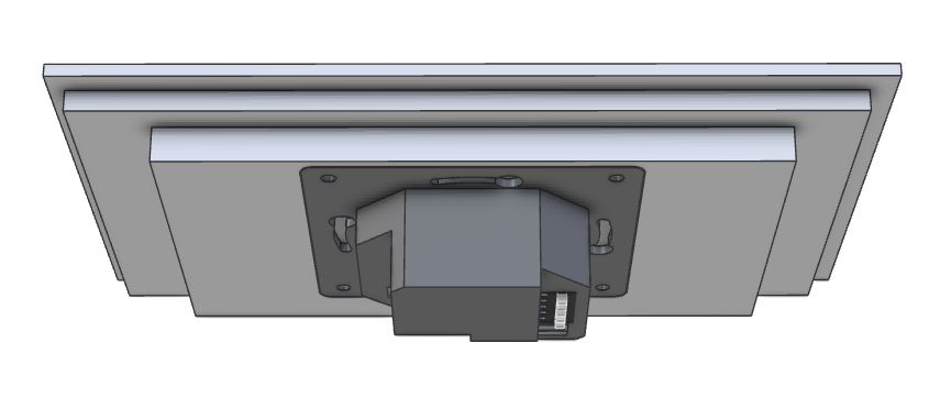
Fig. 5: Oblique view of the panel from above
The panel itself can be secured to the base after snapping it into place using two small screws, which are included in the package.
The screws are inserted from the underside of the panel and require a TORX T6 screwdriver; their locations are shown in Fig. 6. 
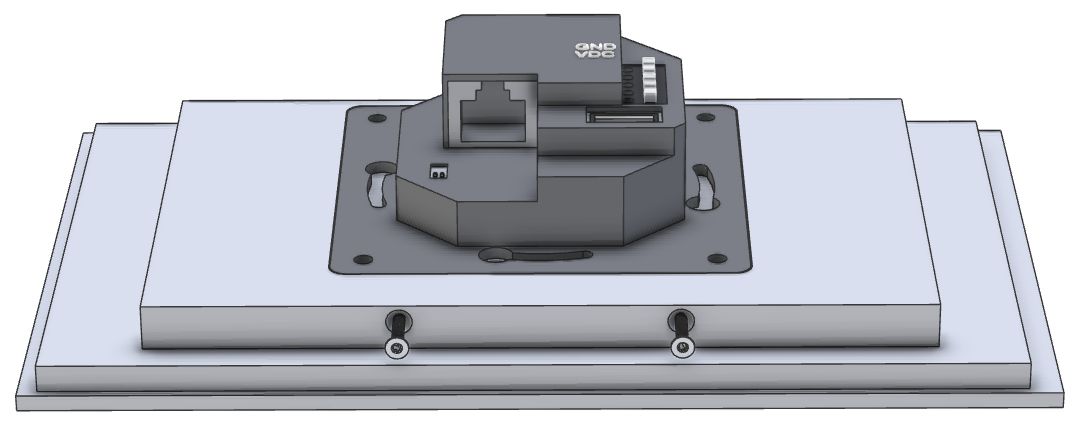
Fig. 6: Location of the two screws for securing the panel to the base
Mounting on a drywall, wood, etc.
Note: For wall mounting where no junction box is installed, you can order a wall mounting bracket (TXN 055 22.95), which is screwed into the wall. The base is then screwed into the bracket, and the installation proceeds as described for wall mounting on a brick wall.
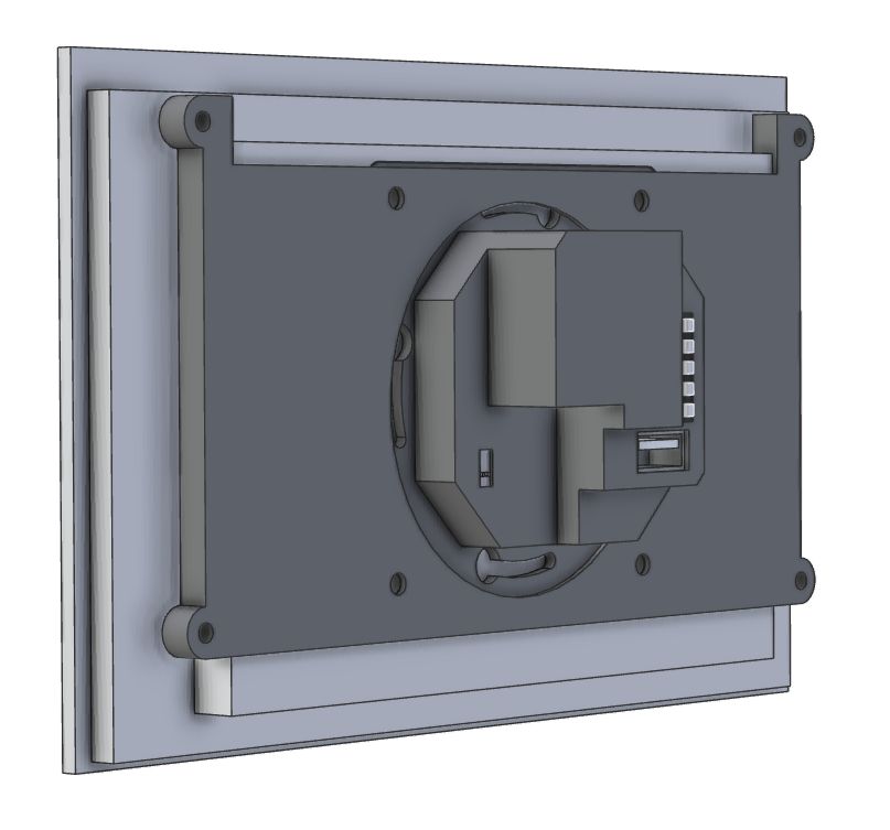
Fig. 7 Illustration of the ID-74 panel with a wall-mount bracket (the wall-mount bracket is shown in dark gray)
Dimensions of the ID-74 control panel
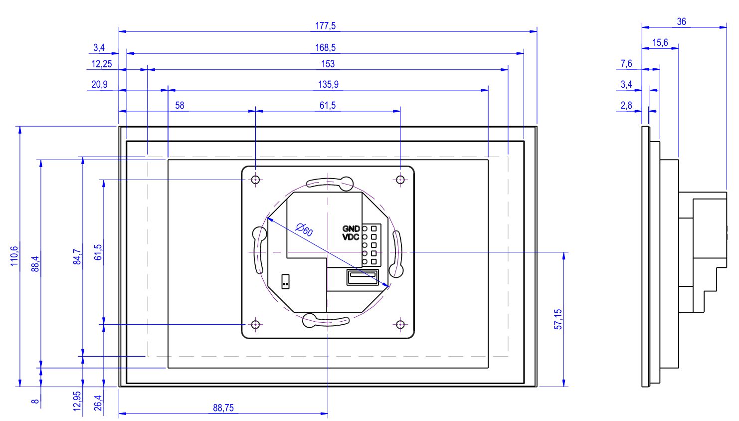
Fig. 8 Dimensions of the ID-74 operator panel (when mounted on a brick wall using a standard electrical box)
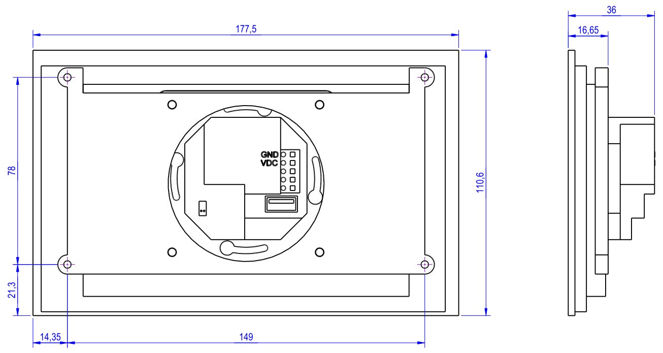
Fig. 9 Dimensions of the ID-74 operator panel (when mounted on a drywall using the TXN 055 22.95 mounting bracket)
Specifications
|
Power connection |
Push-in spring terminal blocks |
|
IP rating |
IP20 |
|
Input voltage |
24 ÷ 48 V DC |
|
Internal protection |
No |
|
Power consumption |
5 W Max |
|
Maximum weight |
0,3 kg |
|
Dimensions |
176 x 109 mm |
|
Product standards |
EN 60730 |
Operating Specifications
| Operating Temperature Range |
0 °C to + 45 °C |
| Storage Temperature Range |
-20 °C to + 70 °C |
| Operating/Storage Humidity |
5 % to 85 % RH, no condensation |
| Operating position |
vertical |
| Type of Operation |
permanent |
Display Specifications
|
Display |
color TFT IPS |
|
Diagonal size |
7” |
|
Resolution |
1024 x 600 |
|
Brightness |
300 cd/m2 typ. |
|
Touch screen |
capacitive multitouch |