
This article describes the correct examples of powering the modules (both internal and IO circuits) of the TC800 system.
The PW-8901 power supply module has two power level inputs VM and VIO on connector A.
We connect the 24 VDC supply voltage to terminals A1 and A2 (VM+ and VM-), which are used to power the internal circuits of all modules on the bus (i.e. powering processor parts, indicators, etc.).
We connect the 24 VDC supply voltage to terminals A3 and A4 (VIO+ and VIO-), which are used to power the IO parts of the modules - i.e. powering the input and output circuits, powering the relay coils of the OR-8450 module and providing power for galvanically isolated sources for the analog part of the IT-8601 and OT-8651 modules. The required power of the source must be calculated according to the consumption from the VIO level of the individual modules.
Basic TC800 connection, modules powered from one common power supply
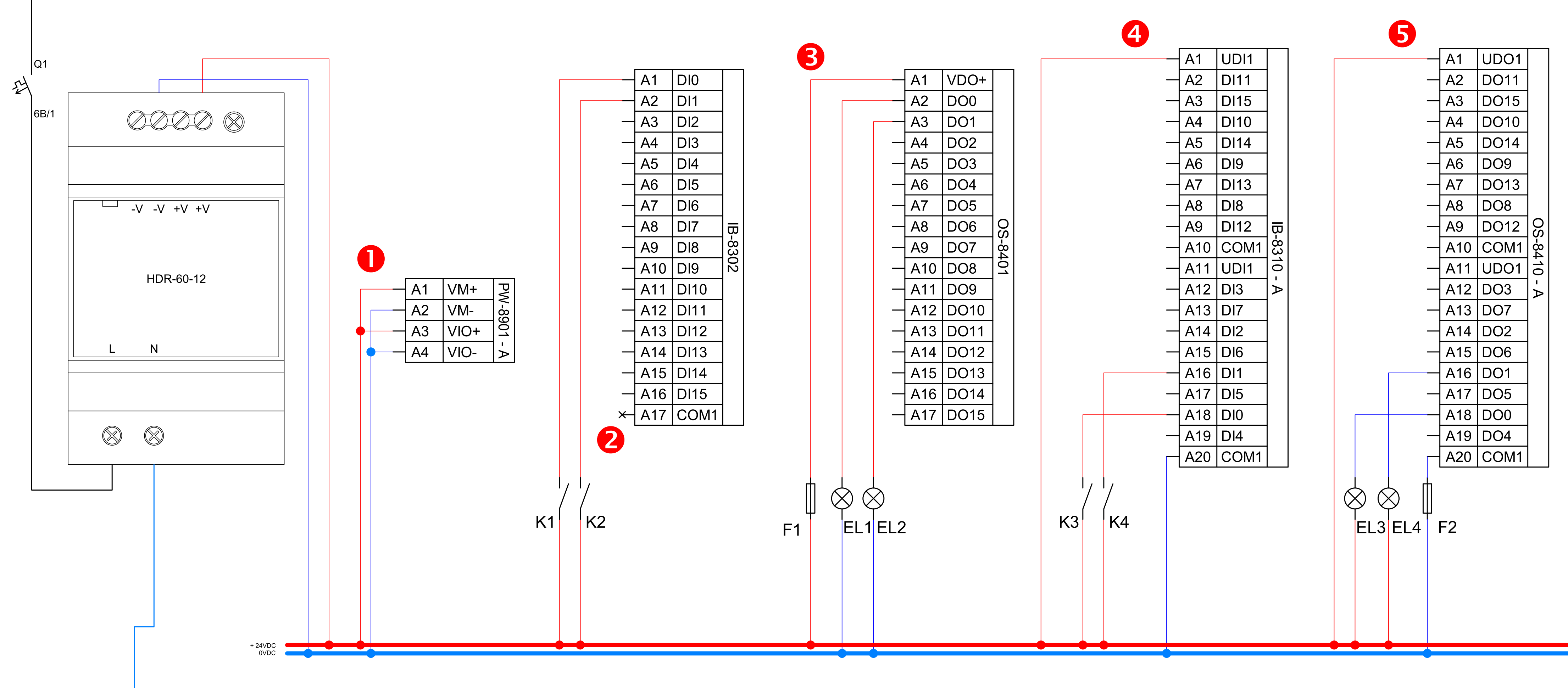
- The power supply of the internal circuits (VM) and the power supply of the IO circuits of the peripheral modules (VIO) are galvanically separated from each other, but it is possible to connect them on the terminal board of the PW-8901 module and power them from one source - this is suitable for smaller applications.
- Terminal A17 (COM1) of the IB-8302 module is internally connected to terminal A4 (VIO-) of the PW-8901 module and must not be connected with an external wire (an unwanted ground loop would occur)
- The internal circuits of the outputs of the OS-8401 module are powered from the VIO level (terminals A3 and A4 of the PW-8901 module), terminal A1 on the OS-8401 module is the power supply of the power circuits of the DOx switches (max. 8 A)
- The IB-8310 module has the power supply of the IO part completely separated from all the circuits of the system, so it requires to supply 24 VDC to the connector (UDI1 and COM1), the COM1 terminal is also a common terminal for DIx.
- The OS-8410 module has the power supply of the IO part completely separated from all the circuits of the system, so it requires to supply 24 VDC power to the connector (UDO1 and COM1), the COM1 terminal is also a common power terminal for DOx.
Connecting the separate power supply of TC800 peripheral modules
IB-8302
The ZD1 power supply is only for powering the internal circuits of the TC800 system
The ZD2 power supply is for powering jointly powered IO parts of peripheral modules, including IB-8302.
The ZD3 power supply to feed the input circuits (excited input current source) of the module's own binary inputs.
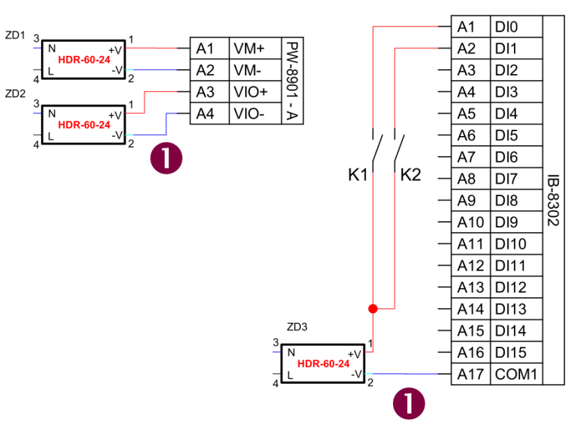
1) ATTENTION! Terminal A17 (COM1) of the IB-8302 module is connected internally (through the system bus) to terminal A4 (VIO-) of the PW-8901 module and must not be connected with an external wire (there would be an unwanted ground loop)
OS-8401
The ZD1 power supply is only for powering the internal circuits of the TC800 system
The ZD2 power supply is for powering jointly powered IO parts of peripheral modules, including OS-8401.
The ZD3 power supply is only for powering the module's switched module loads, max current 8A common terminal VDO+ (A1).
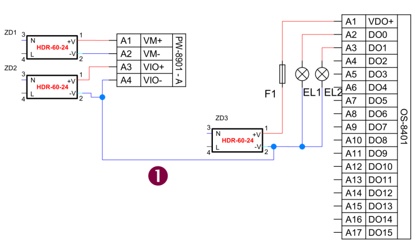
1) For the correct operation of the output power switches of the module, it is necessary to connect the negative terminal ZD3 (the source supplying the switched loads of the module) to the negative terminal of the VIO level (terminal A4 on the PW-8901 module).
IB-8310
The ZD1 power supply is only for powering the internal circuits of the TC800 system
The ZD2 power supply is for powering the jointly powered IO parts of the peripheral modules, it does not apply to the IB-8310 module.
The ZD3 power supply is for powering the IO part of the IB-8310 module and for powering the binary input circuits.
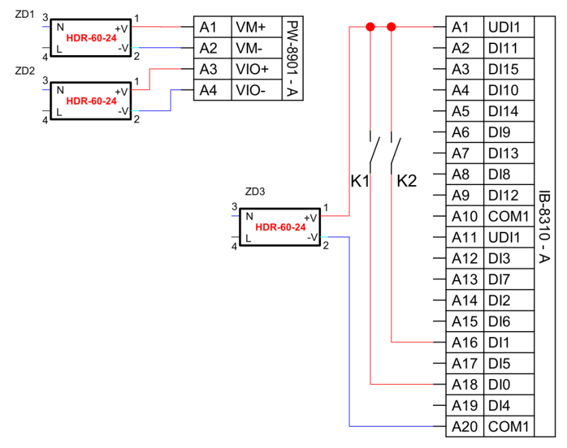
UDI1 terminals on both module connectors (terminals A1, A11, B1, B11) are connected internally and do not need to be connected externally
The COM1 terminals on both module connectors (terminals A10, A20, B10, B20) are internally connected and do not need to be connected externally
OS-8410
The ZD1 power supply is only for powering the internal circuits of the TC800 system
The ZD2 power supply is for powering jointly powered IO parts of peripheral modules, it does not apply to the OS-8410 module.
The ZD3 power supply is for powering the IO part of the OS-8410 module and for powering the module's switched-mode loads, max. current 0.5A through the common terminal UDO1 (A1).
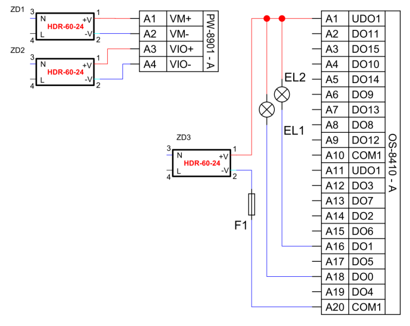
UDO1 terminals on both module connectors (terminals A1, A11, B1, B11) are internally connected and do not need to be connected externally
The COM1 terminals on both module connectors (terminals A10, A20, B10, B20) are internally connected and do not need to be connected externally