
Module properties
The R-IT-0500S wireless input module is equipped with four digital inputs and one input for temperature measurement. The module is powered by a 3V battery type CR-2450.
Digital inputs
5 terminals DI1, DI2, DI3, DI4 and a common COM are reserved for 4 digital inputs on the module. When a COM is connected to one of the DIs, the module sends a DI activation packet (log. 1). Processing and sending time is around 180 ms. Sending a log. 1 is repeated for the period of DI connection with COM with a period of approximately 180 ms. E.g. therefore, more than one packet is sent when the button is pressed for a longer time. Sending stops when the DI contact with COM is broken, no DI deactivation packet is sent (log. 0), only log 1 is transmitted. Log setting. 0 to a variable in the program is solved by software (further).
When DI is continuously activated, a maximum of 101 communications (18 seconds) will take place. The module then stops transmitting to save battery power. When the DI is reactivated continuously, communication 202 takes place (36 seconds).
DIs are independent of each other, the module can send data on the activation of any combination DI1-DI4.
Temperature measurement
The TEMP and GND terminals are intended for the connection of a 12k NTC thermistor. The temperature is sent in a packet together with the data when one of the DIs is activated, or when the timer period has elapsed. The timer is set by placing a jumper on the two pins shown on the module packaging and described directly on the "10 MIN" board. With this setting, the module wakes up every 10 minutes and sends the measured temperature value in degrees Celsius. If the thermistor is not connected, a temperature of 320 ° C is sent. The timer is reset when any DI is activated.
Configuration
The connection of the R-IT-0500S module to the control panel and data collection is performed via the RFox2 master RF-2131 (possibly also SC-1111, for which this example is described), which communicates with the central module via the TCL2 bus.
In the Mosaic in the I / O configurator, the SC-1111 must first be connected to the central module (double-click on "TCL2 bus"). The individual remote R-IT-0500S modules can then be configured to the RFox2 bus (double-click on the "Rfox2 bus").
Each peripheral module is identified by a hardware address, which consists of a four-digit decimal number. The corresponding HW address must be entered for the individual modules in the I / O configurator (each module is added separately). This is stated on the module packaging, or directly on the PCB.
Temperature measurement
When using the built-in timer, there is no need to add code to the program. The module sounds itself every 10 minutes and updates the value of the "Temperature" variable. When any DI is activated, the temperature is also sent and the timer is reset.
Digital inputs
Before using the digital inputs, in addition to configuring the module in the I / O configurator, it is necessary to add a program to reset the variable carrying information about the state of the button. As mentioned above, the module only sends a log. 1 when DI is activated. After a single activation of the button connected to DI, the value of the corresponding variable would remain set to 1. The enclosed function block fb_RFox2_RIT0500S.ST “solves this phenomenon. After receiving the log. 1 sets the corresponding variable back to zero. When DI is activated, it is therefore a variable in log. 1, when DI is inactive, it is in log. 0. In the program, this function block must be called at the beginning of the cycle or before evaluating the state of the keys in order to read the current values.
Examples
During testing, a program was created for reading the temperature and closing the buttons on the device.
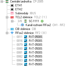
Fig. 1 I/O configurator
Figure 1 shows the control panel used, the SC-1111 connected via the TCL2 bus and the eight configured R-IT-0500S peripheral modules.
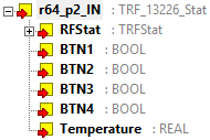
Fig. 2 naming variables
In Fig. 2 to DI1-DI4 correspond to the variables BTN1-BTN4, the temperature is stored in Temperature (one of the peripheral modules, all set the same)
Function block „fb_RFox2_RIT0500s.ST“
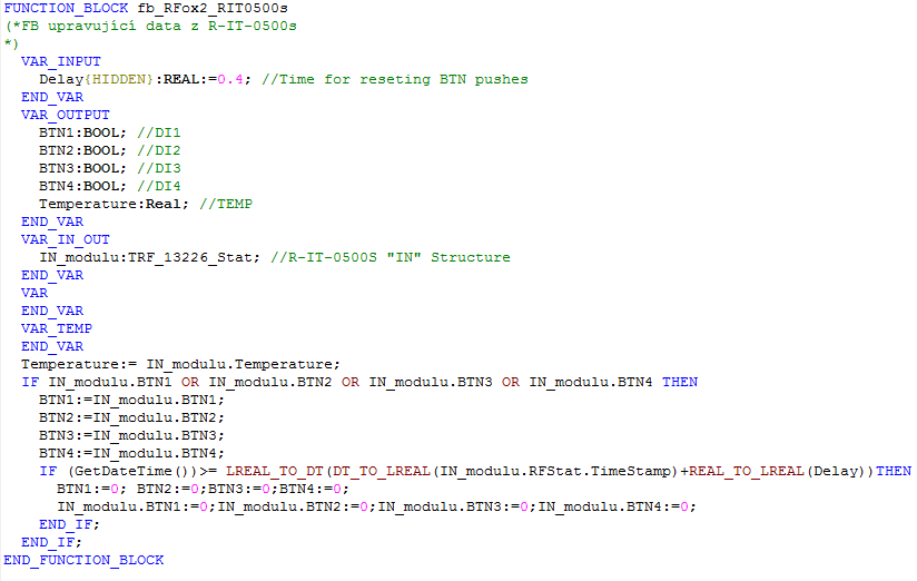
This function block ensures that the state of the BTNx variables corresponds to the state of the button, ie. When pressing the log. 1, otherwise log 0. It is universal for all similar uses.
Custom program
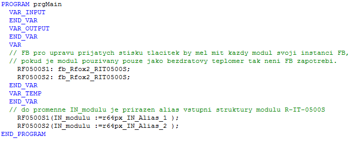
The program only monitors the status of the buttons. For simplicity, only 2 peripheral modules RF0500S1 and RF0500S2 are defined here. After defining the variables, FBs are called to update the BTN1-BTN4 states. When the button is pressed, the temperature is also stored in Temperature, independent of the program.