
This article presents an example of a 12 VDC power supply solution for a Foxtrot system as well as an example of a 12 VDC mains powered, battery backed up solution using a 24 VDC nominal system power supply.
You can find an example of calculating the approximate backup time and the necessary battery capacity for connection according to Fig. 1 in this article.
A MeanWell DDR-15G-24 DC/DC converter can be used to power the Foxtrot system from the 12 VDC (13.8 VDC) level. The module is in the 1M on DIN rail. The input of the module is 12 VDC (range 9 ÷ 36 VDC), the output is 24 VDC, 0.63 A max.
The DRC-40A power supply power supply is a mains switching power supply with a fixed output voltage of 13.8 V, 2.9 A. Used with DC/DC converter to 24 VDC to power Foxtrot control systems that require backup power in the event of a mains power failure using backup 12 VDC voltage.
The power supply does not directly power the control system (connected load). It simultaneously charges (keeps charged) the connected lead-acid battery and, through a 12/24 VDC DC/DC converter, provides a backup supply voltage of 24 VDC for the control system. In the event of a power failure, the power supply continues to supply the load from the connected battery.
The power supply is equipped with two transistor outputs AC OK and Bat Low.
The AC OK output transistor is closed when the correct mains voltage is present at the input of the power supply.
The Batt Low output transistor is closed when the battery voltage is below 11 V (low battery signaling).The outputs are handled by open collector transistors. Outputs are handled by open collector transistors. The emitter (negative terminal of the output) is internally connected to the -V terminal (terminal 1).
The module does not require forced cooling, it is powered from a standard 230 VAC power supply.
When switching the input of the source, it is necessary to take into account the maximum value of the switching current of up to 60 A (more information can be found in this article). Recommended backup fuse T 3.15 A.
The input of the 230 V source should always be treated against overvoltage. The article describes the basic principles of surge protection, including examples of SPD type 3 connection and power supply.
The DRC-40A power supply meets safety transformer requirements and is a safety extra-low voltage (SELV) source.
Tab. 1 Basic parameters of the DRC-40A source
| Input voltage | 90 ÷ 264 VAC |
| Input current type. | 0,6 A / 230 VAC |
| Inrush current (cold start) | max. 60 A / 230 VAC |
| Output voltage | 13,8 VDC |
| Output current | max. 2,9 A |
| Total output power continuous | max. 40,02 W |
| Output short-circuit protection | electronic |
| Switching off the battery at voltage | 10 +/-0,5 V |
| Max. charging current | 1 A |
| Max. switching voltage and current of outputs AC OK, Bat Low | 50 V, 30 mA (outputs open collector) |
| Electrical resistance of input / output insulation | 3000 VAC |
| Operating temperature | -30 °C up to+70 °C (load. characteristics see Fig. 2.) |
| Dimensions |
40 x 90 x 100 mm |
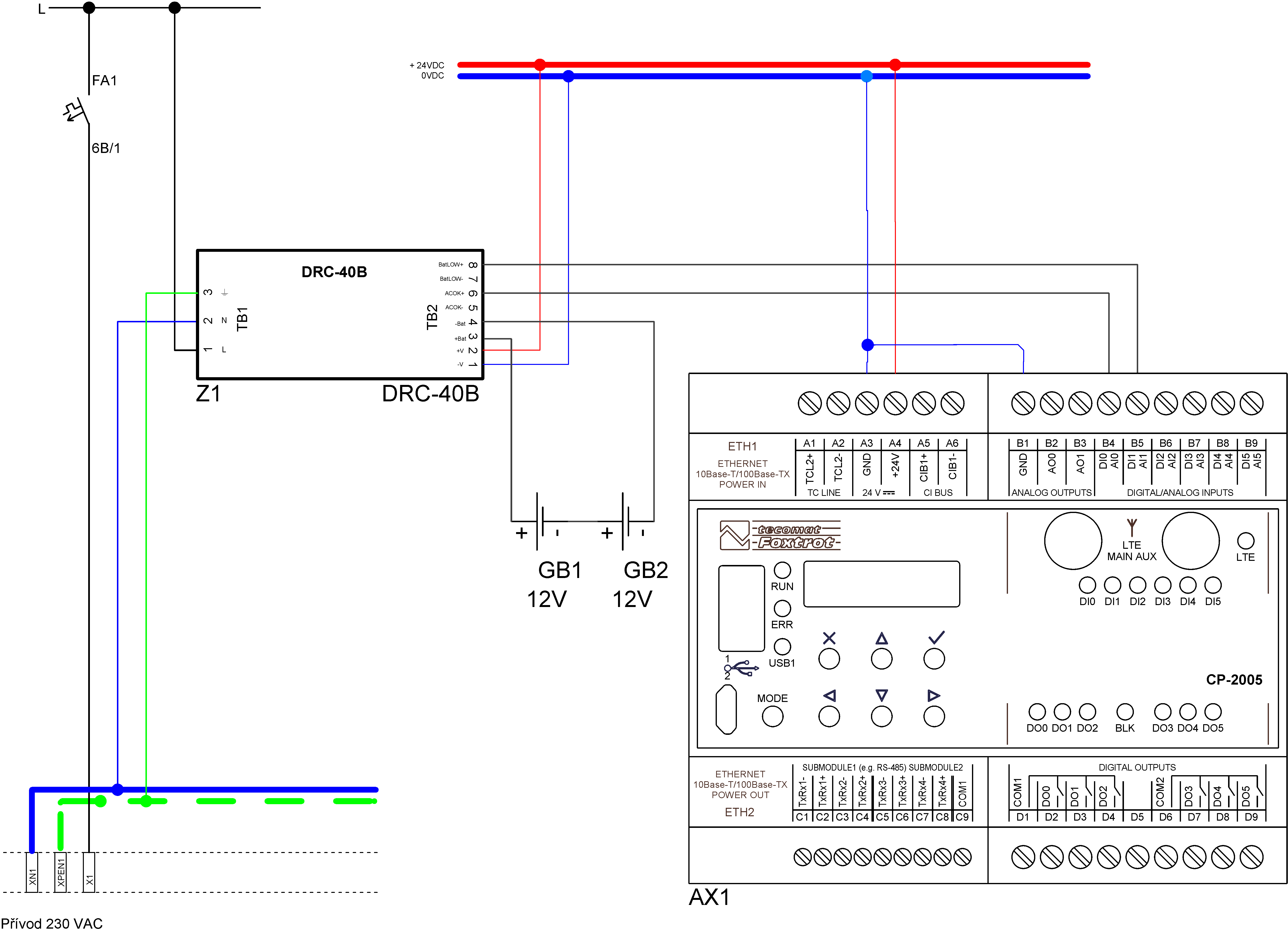
Fig. 1. Example of CP-2005 backup power supply
Notes:
- The CP-2005 module does not have a "potential-free contact" binary input mode, so the AI0 and AI1 configurations are used to measure the resistance range 0 ÷ 2 kΩ and are evaluated as a resistance (almost zero or almost infinity). E.g. CP-2007 has a potential-free contact mode directly, it is possible to use DI mode directly there.
- The switched-off power supply, after connecting only the batteries, does not start supplying power to the output circuits, it must first be connected to the 230 VAC mains, then it works normally even when the mains voltage is disconnected.
- The CP-2005 module powered in this way, when backing up, for example, 2 pcs of 12 V, 9 Ah batteries (eg HR 1234W), will last approximately 55 hours from batteries (when using LTE communication only up to about 3% of the operating time).
-
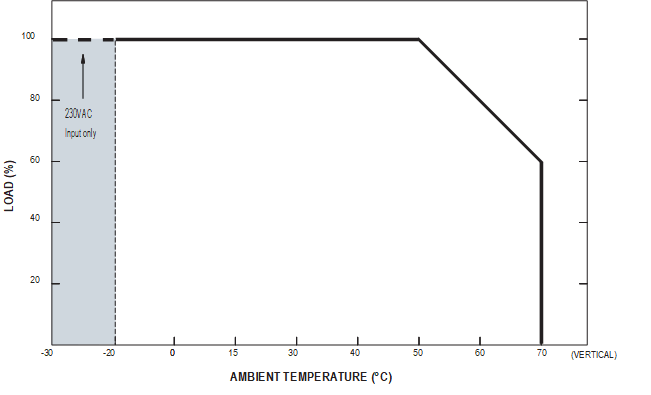
Fig. 2. Load characteristics of the DRC-40A power supply
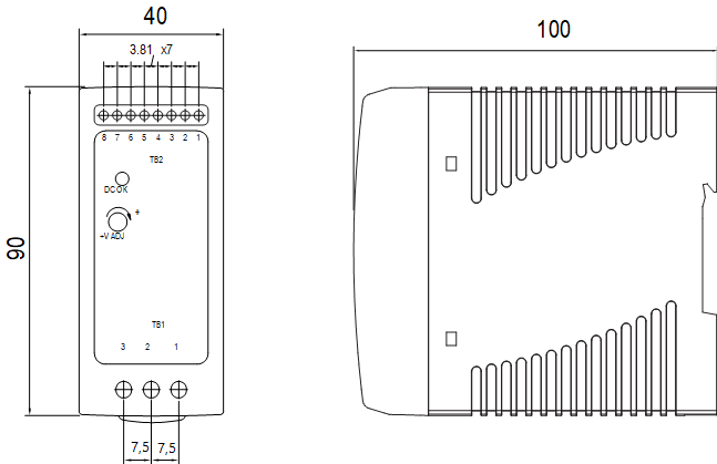
Fig. 3. Front view of the DRC-40A power supply, dimensions of the power supply module
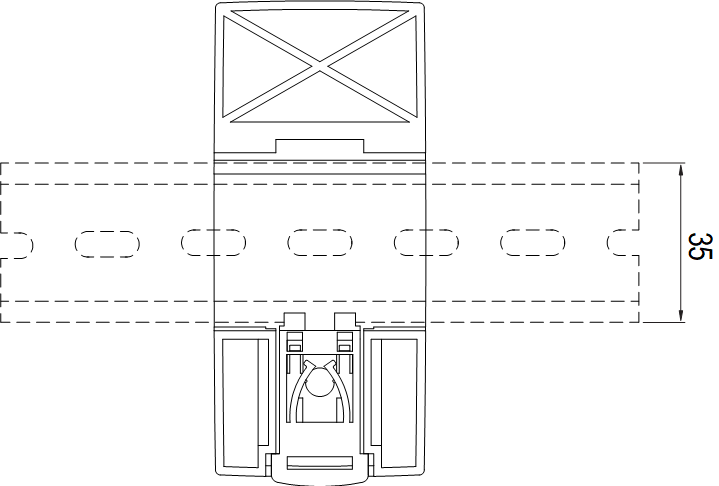
Fig. 4. Placement of the DRC-40A power supply on a DIN rail