
The basic module CP-2080 is the basic module of the Foxtrot 2 control system. It is in standard version on DIN rail, in 6M cover (for dimensions of box see chapter 13.2.2 6M mechanika na DIN lištu), fitted with four removable terminal blocks. It is also equipped with two independent Ethernet interfaces, one USB device interface for connecting the master system and one USB host interface for connecting external memory (USB Flash Drive).
The basic module includes an integrated display of 4 x 20 characters and 7 buttons. In addition to system setup and diagnostics, the display and buttons can also be used in the user program.
The basic module also includes a slot for an additional micro SD card (not available in variants with a WLAN1 interface). Some variants of the basic module are equipped with internal WLAN1 for WiFi network or LTE1 for GSM network (see below).
The TCL2 system bus can be connected to the basic module for communication with the FOXTROT family peripheral modules and the CIB Common Installation Bus® (trademark of Teco a.s., hereinafter referred to as CIB) for communication with CFox family modules.
Optionally, the basic module can be fitted with two serial channel submodules.
For more information on possible casting options, see the introduction to CP-2005.
Fitting I/O
Power supply 24 VDC, power consumption max. 10 W (for power supply see chap. 2.2)
DI0 ÷ DI3 4 DI, with galvanic isolation, potential-free contact, optionally with counter function
DO0 ÷ DO5 6 relay outputs, galvanically isolated from other circuits, 3 A per output
DO6, DO7 The 2 24 VDC transistor outputs, optionally PWM, switch against the SGND, 1 A ground
ETH1 Ethernet 10/100 Mbit (standard RJ-45 connector), galvanically isolated from other circuits, see chapter 2.4.1xx, including external power input (power injector)
ETH2 Ethernet 10/100 Mbit (standard RJ-45 connector), galvanically isolated from other circuits, see chapter 2.4.1xx, including external power output (for external panels, etc.)
CH1. CH2 Submodule 1, serial channels according to mounted submodule, see chap. 2.3.1xx
CH3, CH4 Submodule 2, serial channels according to mounted submodule, see chap. 2.3.1xx
USB1 USB host interface with type A connector for external memory (flashdisk)
USB2 USB device interface with micro B connector for Mosaic development environment
|
Binary inputs DI0 ÷ DI3 |
|
| Input type | Potential-free contact, with a common minus ministry |
| Input current at log.1 | -1 mA |
| Minimum pulse width | 500 µs |
Relay outputs
DO0 ÷ DO2, common terminal outputs, continuous current output 3A, short-time 5A, maximum continuous current for the common terminal COM1 is 10A, podrobnější informace o kontaktech relé
the isolation voltage between the output groups and the other circuits is 3750 VAC, ie safe circuit separation
DO3 ÷ DO5, common terminal outputs, continuous current output 3A, short-time 5A, maximum continuous current for the common terminal COM2 is 10A, podrobnější informace o kontaktech relé
The principles of protection and use for capacitive and inductive loads can be found in the chapter 13.7.1 Ochrana výstupních prvků (relé,...).
Transistor outputs
2x transistor output switching against countries SGND, switching element max. Current 3A, continuous current output 1 A, switches are equipped with internal protection against current and thermal overload.
Terminal Blocks of the basic module are connectors with a cage clamp with a pitch of 5.08 mm. More detailed terminal parameters are given in chapter 13.3.1 Konektory se šroubovými svorkami, rozteč 5,08mm, moduly na DIN lištu.
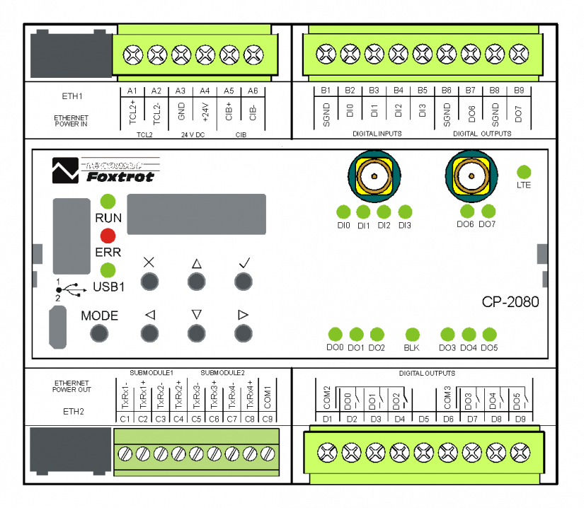
Fig. 1. CP-2080 module