
The basic module CP-2007 is the basic module of the Foxtrot control system of the second generation. It is in standard version on DIN rail, in 9M cover (for dimensions of box see chapter 13.2.1 9M mechanika na DIN lištu), it is equipped with six removable terminal blocks.
For more information on possible casting options, see the introduction to CP-2005.
Fitting I/O:
Power supply 24 VDC, power consumption max. 10W (see chapter 2.2 for information on power supply)
AI0/DI0 ÷ AI5/DI5 6 analog inputs, without galvanic isolation with optional DI function:
ranges: Ni1000, Pt1000, 2 kΩ, 200 kΩ, 0÷20 mA, 4÷20 mA, NTC, DI 24 V
AI6/DI6 ÷ AI7/DI7 2 analog inputs, without galvanic isolation with optional DI function:
ranges: Ni1000, Pt1000, 2 kΩ, 200 kΩ, NTC, DI 24V
AI8/DI8 ÷ AI13/DI13 6 analog inputs, without galvanic isolation with optional DI function:
ranges: Ni1000, Pt1000, 2 kΩ, 200 kΩ, 0÷20 mA, 4÷20 mA, NTC, DI 24 V
DI14 binary input 230 V AC (eg HDO), galv. separate
AO0/DO11÷AO1/DO12 2 analog outputs, without galvanic isolation, range 0 ÷ 10 V, PWM
AO2/AI6 ÷ AO3/AI7 2 analog outputs, without galvanic isolation, range 0 ÷ 10 V, alternatively with inputs AI6 / DI6 and AI7 / DI7 (set by jumper)
DO0 ÷ DO10 10 relay outputs, galvanically isolated from other circuits
3 A output contact (DO6 is equipped with a more powerful 16 A contact)
ETH1 Ethernet 10/100 Mbit (standard RJ-45 connector), galvanically isolated from other circuits, see chapter 2.4.1xx, including external power input (power injector)
ETH2 Ethernet 10/100 Mbit (standard RJ-45 connector), galvanically isolated from other circuits, see chapter 2.4.1xx, including external power output (for external panels, etc.)
CH1. CH2 Submodule 1, serial channels according to mounted submodule, see chap. 2.3.1xx
CH3, CH4 Submodule 2, serial channels according to mounted submodule, see chap. 2.3.1xx
USB1 USB host interface with type A connector for external memory (flashdisk)
USB2 USB device interface with micro B connector for Mosaic development environment
| Analog inputs | AI0 ÷ AI5
AI8 ÷ AI13 |
AI6 ÷ AI7 |
| temperature sensorPt1000, W100=1,385 or 1,391 | -90 °C ÷ +270 °C | -90 °C ÷ +270 °C |
| temperature sensorNi1000, W100=1,500 or 1,617 | -60 °C ÷ +155 °C | -60 °C ÷ +155 °C |
| temperature sensor KTY81-121 | -55 °C ÷ +125 °C | -55 °C ÷ +125 °C |
| temperature sensor NTC 12k | -55 °C ÷ +125 °C | -55 °C ÷ +125 °C |
| resistive ranges | 0 ÷ 2 kΩ (OV2000)
0 ÷ 200 kΩ (OV200000) |
0 ÷ 2 kΩ (OV2000)
0 ÷ 200 kΩ (OV200000) |
| voltage ranges | 0 ÷ 10 V
0 ÷ 2 V |
0 ÷ 10 V
0 ÷ 2 V |
| current ranges | 0 ÷ 20 mA
4 ÷ 20 mA |
- |
| Input resistance for current ranges | 100 Ω | - |
| Internal voltage for resistance sensors |
9,194 V |
|
| Channel transfer time |
typ. 20 μs |
|
| Recovery time for each channel |
cca 850 μs |
|
comment:
-
The current ranges require the appropriate input jumper to be inserted. The jumpers are located under the cap describing the numbers and terminal names (above connector B and C).
| Binary inputs | DI0 ÷ DI3, DI6, DI7, DI10 ÷ DI13 | DI4, DI5, DI8, DI9 | DI14 |
| Input voltage for log. 0 |
max. +5 V DC |
max. 120 V AC | |
| Input voltage for log. 1 |
min. +15 V DC max. +30 V DC |
min. 200 V AC
max. 250 V AC |
|
| Input current for log. 1 |
typ. 5 mA |
typ. 5 mA | |
| Minimum pulse width | 500 µs | 500 μs | - |
| Max. frequency | - | 1 kHz | - |
Comment:
-
The inputs DI3 ÷ DI5 and DI8 ÷ DI12 enable the function of capturing short pulses. This function extends the selected level of input signal, ensuring that we do not lose an individual pulse at the input, shorter than the cycle time of the program (eg to connect the pulse outputs of the flowmeters, etc.).
-
Inputs DI4, DI5, DI8 and DI9 can be set to counter mode, eg for pulse flow meter outputs, etc.
Analog output AO0, AO1
| Output range | 0 ÷ 10 V |
| Maximum output value | 105 % upper limit of output range |
| Maximum output current | 10 mA |
| Max. load capacity | 50 nF |
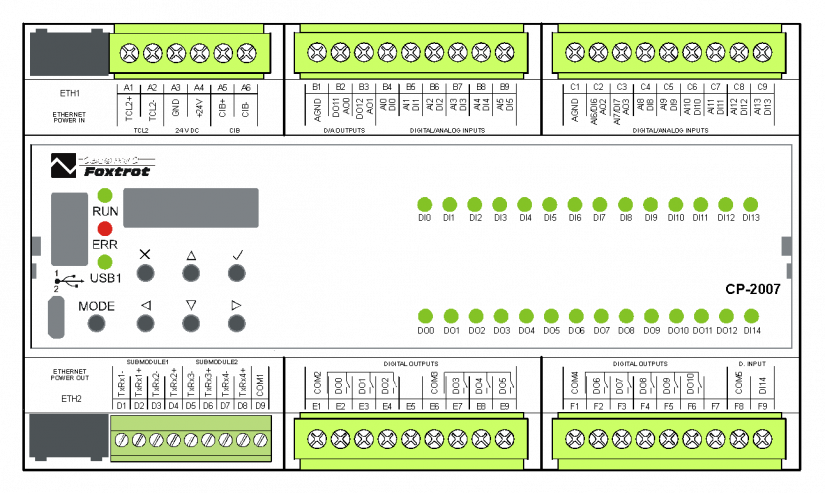
Fig. 1. Module CP-2007
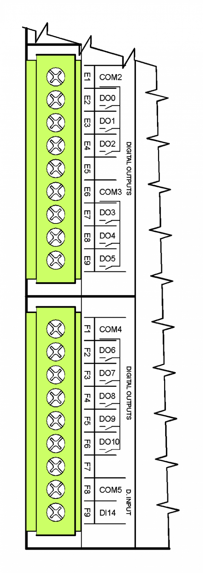
Fig. 1.1 Relay outputs of CP-2007 module
DO0 ÷ DO2, common terminal outputs, continuous current output 3A, short-time 5A, maximum continuous current for the common terminal COM2 is 10A, podrobnější informace o kontaktech relé
the isolation voltage between the output groups and the other circuits is 3750 VAC, ie safe circuit separation
DO3 ÷ DO5, common terminal outputs, continuous current output 3A, short-time 5A, maximum continuous current for the common terminal COM3 is 10A, podrobnější informace o kontaktech relé
the isolation voltage between the output groups and the other circuits is 3750 VAC, ie safe circuit separation
DO6, output with common terminal COM4, continuous current output 10 A, short term 16 A, max. continuous current for the common terminal COM4
is 10 A,podrobnější informace o kontaktech relé
DO7 ÷ DO10, outputs with common terminal COM4, continuous current output 3 A, short-time 5A, max. continuous current for the common terminal COM4 is 10 A, podrobnější informace o kontaktech relé
the isolation voltage between the output groups and the other circuits is 3750 VAC, ie safe circuit separation
DI14, 230 VAC input, especially suitable for HDO signal connection, see chapter 12.4.1 Snímání HDO signálu, základní modul CP-1006
The principles of protection and use for capacitive and inductive loads can be found in the chapter 13.7.1 Ochrana výstupních prvků (relé,...).
Terminal Blocks of the basic module are connectors with a cage clamp with a pitch of 5.08 mm. More detailed terminal parameters are given in chapter 13.3.1 Konektory se šroubovými svorkami, rozteč 5,08mm, moduly na DIN lištu
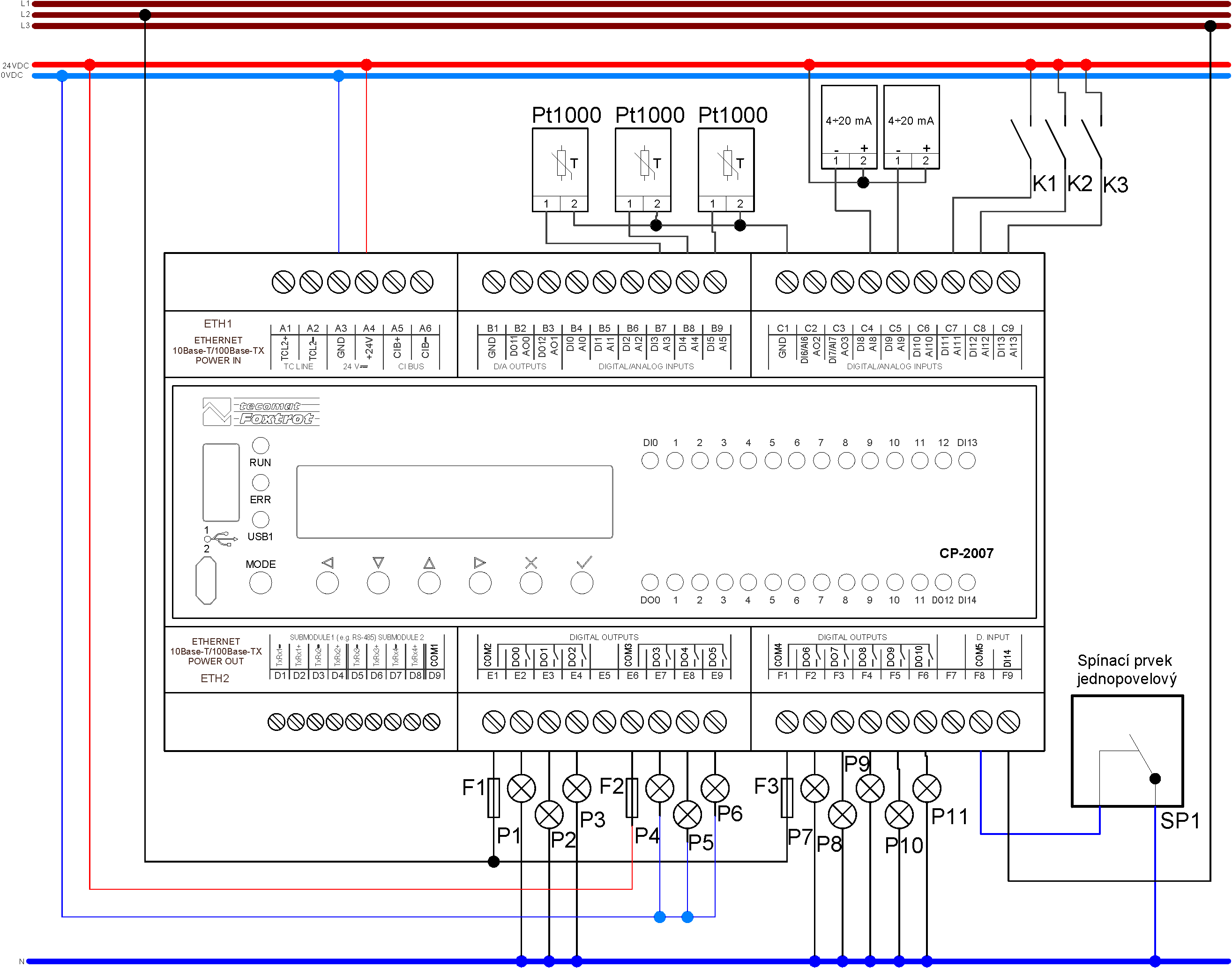
Fig. 2 Basic example of basic module CP-2007
Wiring Notes:
-
The relay output groups (DO0 ÷ DO2, DO3 ÷ DO5, DO6 ÷ DO10) can switch circuits powered from different sources. Groups are separated by isolation corresponding to safe circuit separation.
-
The DO6 output is fitted with a relay with a reinforced contact 16A (short-term 80A).
-
The optional AI input functions are set from the programming environment, while only 20 mA current ranges are set by jumpers located under the right top lid (above terminal box).
-
The TCL2 bus is firmly terminated on the base module and must always be at the end of the bus line (see chapter 3.3 Sběrnice TCL2 – zásady projektování a instalace).
-
Module power supply, interface TCL2, CIB and CH1 have common signal ground, terminal GND (terminal A3). This terminal is galvanically connected to the common AI / AO terminal (terminals B1 and C1).
-
Analog inputs are configured as inputs with a common negative GND terminal.
-
We do not connect terminals A3 and B1 and C1 (GND) in the application. The C1 terminal is used in the case of 0 ÷ 20 mA or 4 ÷ 20 mA current loops powered from another 24 VDC source galvanically isolated from the source supplying the base module itself.
-
Input DI14 is a 230V AC input, the input is also rated for 400VAC (eg, HDO signal processing). The input is galvanically isolated from other insulation circuits corresponding to safe circuit separation.