
The CP-2000 is the simplest version of the basic home installation module.
The base module is powered by a 24 VDC power supply.
Both CIB branches (connector B) are supplied from the base module, which means that no CIB bus isolation module is already in use, the isolation circuits for the two busbars are integrated directly into the CP-2000 basic module.
The TCL2 system bus is connected to connector A (especially for connecting external master modules).
We connect inputs and outputs to connectors E and F: 4 universal AI / DI (contact, NTC, Pt1000, Ni1000), 2 separate relay outputs, inputs HDO and IN 230 VAC input (230 VAC standard binary input).
Backup of internal data and time CP-2000 during power failure.
When switching off the power supply CP-2000, the selected user data and clock are backed up. Backup is provided by Li-Ion battery. When power is restored, the battery is recharged and ready to back up. The battery requires no maintenance.
The Li-Ion battery lasts about 500 hours.
Fitting I/O
Power supply 24 VDC, power consumption max. 70 W (see chapter 2.2 for information on power supply)
AI0/DI0 ÷ AI3/DI3 4 analog inputs, without galvanic isolation with optional DI function:
ranges: Ni1000, Pt1000, OV1000, NTC, DI
DO0 relay output, galvanically isolated from other circuits Relay 16 A equipped with reinforced changeover contact
DO1 relay output, galvanically isolated from other circuits
relay 5 A make contact
ETH1 Ethernet 10/100 Mbit (standard RJ-45 connector), galvanically isolated from other circuits, see chapter 2.4.1xx, including external power input (power injector)
ETH2 Ethernet 10/100 Mbit (standard RJ-45 connector), galvanically isolated from other circuits, see chapter 2.4.1xx, including external power output (for external panels, etc.)
CH1 RS-232 interface without galvanic isolation
CH2. CH3 Submodule 1, serial channels according to mounted submodule, see chap. 2.3.1xx
CH4, CH5 Submodule 2, serial channels according to mounted submodule, see chap. 2.3.1xx
USB1 USB host interface with type A connector for external memory (flashdisk)
USB2 USB device interface with micro B connector for Mosaic development environment
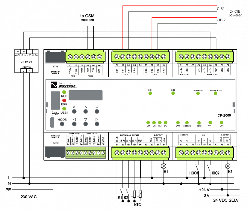
Fig. 1. Example of powering the CP-2000 without backup
Comment:
-
We recommend a 24 VDC stabilized power supply, meeting SELV conditions, we recommend the DR-60-24 by default. The power consumption of CP-2000 is given by the sum of the power consumption of the central unit's own circuits (type 5W) and the total power of all CFox modules connected to both CIB branches.
-
The terminal block B outputs both branches of the CIB bus including power with a maximum current of 1 A for each branch.
-
Inputs AI / DI0 to AI / DI3 are universal inputs (contact, temperature sensor NTC, Pt1000, Ni1000)
-
input IN 230 VAC (terminals F1 and F2) is designed for monitoring the presence of mains supply 230V. It is a standard 230V input, galvanically isolated
-
Inputs HDO1 and HDO2 (terminals F4, F5 and F6) are intended for connection of switching element outputs (Incorrect HDO receiver). The input can withstand even poorly wired HDO in the home installation without damage.
-
Outputs DO0 and DO1 are standard electromechanical relays 16 A, respectively. 3A on contact, galvanically isolated from other circuits.