
All frames of one PLC assembly (ie all frames controlled by one central unit located in one of the frames) must be interconnected by bus cables, which are connected to the connectors on the left edge of the frame marked BE1 and BE2 (BUS EXTENSION). The connection of the frames must be done linearly (ie the frames are connected in series one after the other, it is not possible to implement a branch).
Free end frame connectors must be fitted with KB-0201 termination modules (2 KB-0201 modules always required for each TC700 assembly are supplied in the TXN 102 01 set). No connector BE1 or BE2 to remain unmounted!
In the case of the implementation of a second bus connected to the central unit via the MR 0154 submodule, this submodule is usually located at the end of the line. In this case, we must not forget the termination, which is realized by connecting the appropriate terminals of the connector (see chapter 3.11.1).
For the single-frame assembly, both BE1 and BE2 connectors of the KB-0201 bus termination modules are fitted.
Multi-frame assemblies can be implemented with the connection of frames, including power supply (we will use one source for powering more frames), without power supply (each frame has its own source), or a combination of both variants.
We connect the individual frames with KB-0203 cables (connection of the communication bus only) or KB-0202 cables (connection including power supply - see below). In the case of a greater distance, we connect only the communication bus using the connection terminal block KB-0204 (Fig.3.1, Tab.3.1 and Tab.3.2). We will use the same terminal block to connect the frame to the serial channel of the central unit equipped with the MR-0154 submodule.
The frames can also be interconnected by optical cables or a combination of optical and metallic cables. To connect with an optical cable, it is necessary to insert the connection modules KB0250, resp. KB0251. We connect the modules with a duplex optical cable KB0260, resp. KB0261 (fig.3.10.7.2, fig.3.10.7.3, tab.3.10.7.1).
The optical cable guarantees galvanic isolation and therefore the power supply must be located in the following frame. A detailed procedure for calculating the maximum lengths of optical cables is given in the documentation TXV 004 02, chap. 3.3).
Tab.3.10.7.1 Order numbers of cables by length
| Length[m] | KB-0202 | KB-0203 | KB-0260 | KB-0261 |
| 0,25 | TXN 102 02.01 | TXN 102 03.01 | - | - |
| 0,5 | TXN 102 02.02 | TXN 102 03.02 | - | - |
| 0,75 | TXN 102 02.03 | TXN 102 03.03 | - | - |
| 1 | TXN 102 02.04 | TXN 102 03.04 | TXN 102 60.04 | TXN 102 61.04 |
| 2 | - | TXN 102 03.08 | - | - |
| 3 | - | TXN 102 03.12 | - | - |
| 5 | - | - | TXN 102 60.20 | TXN 102 61.20 |
| 10 | - | - | TXN 102 60.30 | TXN 102 61.30 |
| 20 | - | - | TXN 102 60.34 | TXN 102 61.34 |
| 50 | - | - | - | TXN 102 61.46 |
| 100 | - | - | - | TXN 102 61.56 |
Note: Other lengths can be agreed with the sales department.

Fig.3.10.7.1 Connection of PLC frames with metal cables
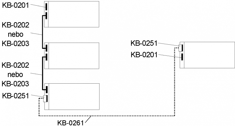
Fig.3.10.7.2 Connection of PLC frames with metallic and optical cables
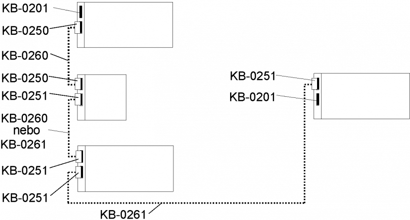
Fig.3.10.7.3 Connection of PLC frames by optical cables
3.10.7.1 Power connection (using KB-0202 cables)
The connection of RM-794x frames, including power supply, is obligatorily realized with the KB-0202 cable (order no. TXN 102 02.01 to .04). No other cable (eg longer than specified by the manufacturer) may be used. With this solution, we can use one source to power multiple frames (according to the consumption of used modules). Unused bus extension connectors (BE1 or BE2) on the end frames of the assembly must always be fitted with KB-0201 bus termination modules. The total length of all power cables (ie the combined length of all power cables connecting the frames of one assembly) must not exceed 10 m.
| Cabe order number | Cable length |
| TXN 102 02.01 | 25 cm |
| TXN 102 02.02 | 50 cm |
| TXN 102 02.03 | 75 cm |
| TXN 102 02.04 | 100 cm |
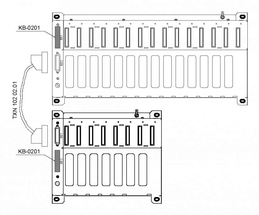
Fig.3.10.7.1 Multi-frame assembly - connection to the power supply
3.10.7.2 Connection without power supply (using cables KB-0203)
The connection of RM-794x frames without power supply is realized by the cable KB-0203 (order no. TXN 102 03.xx), or the customer can make the cable himself (see the following chapter). In this solution, we must use the source in each frame. Unused bus extension connectors (BE1 or BE2) on the end frames of the assembly must always be fitted with KB-0201 bus termination modules.
| Cable order number | Cable length |
| TXN 102 03.01 | 25 cm |
| TXN 102 03.02 | 50 cm |
| TXN 102 03.03 | 75 cm |
| TXN 102 03.04 | 100 cm |
| TXN 102 03.08 | 200 cm |
| TXN 102 03.12 | 300 cm |
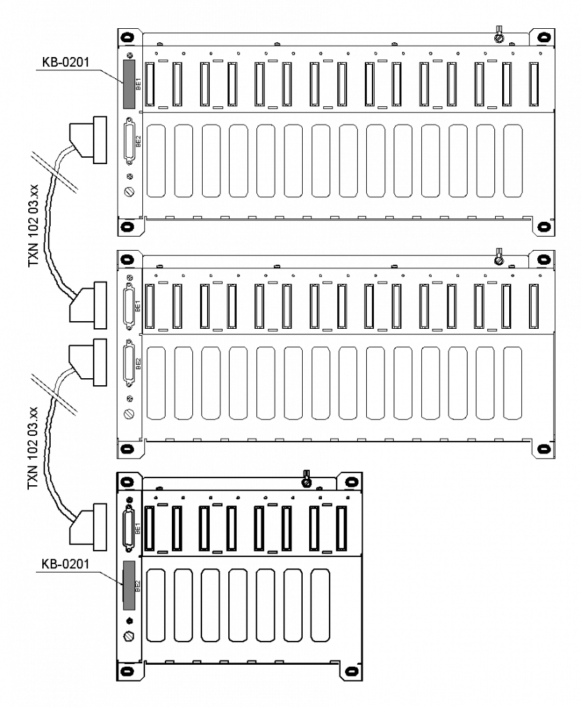
Fig.3.10.7.2 Multi-frame assembly - connection without power supply
Max. the total length of the bus (ie the summed length of all cables connecting the frames of one assembly) can be 400 m. For possible use, the following Fig. 3.10.7.3 shows the connection of frames without power supply (internal connection of the communication part of cable KB-0203). The cable is connected at both ends to D-sub 25-pin connectors, plugs.

Fig.3.10.7.3 TC700 frame connection cable connection without power supply (com. Part of cable KB-0203)
3.10.7.3 Connection without power supply (use of common cables for RS-485 and KB-0204 modules)
The connection of RM-794x frames without power supply is realized by the connection module KB-0204 (order no. TXN 102 04). In this solution, we must use the source in each frame. Unused bus extension connectors (BE1 or BE2) on the end frames of the assembly must always be fitted with KB-0201 bus termination modules.
The frame connection cable can also be made at the installation site (due to the cable being routed through the switchboard glands, etc.). The cable must be shielded, for communication (signals TCL2 +, TCL2–) there must be a twisted pair. It is necessary to use a cable suitable for RS-485 communication (preferably STP cables can be used for structured cabling). Selected recommended cables are listed eg in chapter 3.6.2. Max. the total length of the bus (ie the summed length of all cables connecting the frames of one assembly) can be 400 m. The cable is connected to the screw terminals at both ends. The cable shield must be connected to the connector cover (terminal A4) on one side of the cable only. The signal ground (GND) must be connected, in case of using a cable with two twisted pairs, both wires can be connected to the GND terminal (A3). The cable connection is shown in Fig. 3.10.7.4.

Fig.3.10.7.4 Connection of TC700 frame connection cable without power supply using KB-0204 modules

Fig.3.10.7.5 Module KB-0204 – terminal arrangement
3.10.7.4 Connection options (distributed solution, extension) of the TC700 system - summary.
The following table summarizes the possible ways of connecting TC700 frames to larger assemblies. The above connection options can of course be combined with each other:
| solution | 1 | 2 | 3 | 4 | 5 | 6 | 7 |
| HW | KB-0202 | KB-0203 | KB-0204 | KB-0250 | KB-0251 | KB-0252 | MR-0154 |
| Transmission medium | System cable | System cable | Twisted pair | Optical cable | Optical cable | Optical cable | Twisted pair |
| Power distribution | YES | NO | NO | NO | NO | NO | NO |
| Galvanic separation of the bus | NO | NO | NO | YES | YES | YES | YES |
| Used cable | KB-0202 | KB-0203 | According to specification RS-485 | KB-0260 | KB-0261 | Standard patch cable ST-ST | According to specification RS-485 |
| Connector | Dsub 25 | Dsub 25 | Screw terminals | Duplex Versatile Link | Duplex Versatile Link | 2x ST | Screwless terminals |
| Attenuation approx | - | - | - | 220dB/km | 8dB/km | 3,5 dB/km | - |
| Wavelength | - | - | - | 660 nm | 660 nm | 820 nm | - |
| Fiber type | - | - | - | POF diameter
1 mm |
HCS® diameter 200 μm | glass multimode 62.5/125 mm | - |
| Max. number of I / O modules per CP | 63 | 63 | 63 | 63 | 63 | 63 | +64 |
| Max. length of one bus segment | 10 m | 400 m | 400 m | max. 40 m | max. 570 m | max. 1,7 km | 400 m |
| Max. total bus length | 10 m | 400 m | 400 m | By number of segments | By number of segments | By number of segments | 400 m |
| Detailed information can be found | chap. 3.10.7.1 | chap. 3.10.7.2 | chap. 3.10.7.3 | TXV 004 02, chap. 3.3 | TXV 004 02, chap. 3.3 | TXV 004 02, chap. 3.3 | TXV 004 02, chap. 3.3 |
Notes on individual solutions:
-
Basic connection method including power supply. Suitable for assemblies with several frames in one cabinet. Efficient use of assembly power supplies (up to 2 RM-7942 frames per 50W power supply). Limited by max. Bus length.
-
Interconnection in case of greater distance between frames - control system distributed in several cabinets in technology, etc. Each frame must have its own source. Interconnection with standard cables terminated with 25-pin Dsub connectors.
-
Similar to solution 2, but allows the use of any cable (meeting the requirements for the RS-485 bus), run through channels, through bushings. The cable is always connected to the terminal block of the KB-0204 module for the TC700 frame.
-
Similar to solution 2, but allows the use of any cable (meeting the requirements for the RS-485 bus), run through channels, through bushings. The cable is always connected to the terminal block of the KB-0204 module for the TC700 frame.
-
Long distance connections. Since the lengths of the individual segments add up, we can reach up to km of the bus length of the entire system. The optical cable guarantees galvanic isolation and therefore a power supply must be located in the frame connected by the optical cable. A detailed procedure for calculating the maximum lengths of optical cables is given in the documentation TXV 004 02, chap. 3.3).
-
Long distance connections (best solution). Since the lengths of the individual segments add up, we can reach up to km of the bus length of the entire system. The optical cable guarantees galvanic isolation and therefore a power supply must be located in the frame connected by the optical cable. A detailed procedure for calculating the maximum lengths of optical cables is given in the documentation TXV 004 02, chap. 3.3).
-
Submodule MR-0154 installed in communication channel CH2 (no other channel can be used!) Of central unit CP-7002, CP-7003 (in EIO mode) allows to connect to one central unit another 64 peripheral modules on the other bus (central unit allows by default on its bus to serve 63 peripheral modules, so we have a total of 63 + 64 = 127 peripheral modules). At the same time, galvanic separation of both buses is ensured.