C-WS-0001R is an indoor touch wall controller. It contains a light intensity sensor, a universal AI input for connecting other temperature sensors (e.g. floor temperature, outdoor temperature). Alternatively, it is equipped with a display, temperature, humidity, air quality sensor, RFID reader and 2-8 buttons.

Fig. 1 Module C-WS-0001R
Variant HW configuration
The module number defines its HW configuration, e.g. C-WS-0001R.x1.6SHN. Automatic loading of the module configuration is only supported for PLC Foxtrot 2, alternatively it can be set manually in the configuration dialog.
| x | mechanical design of glass | |||
|---|---|---|---|---|
| 1 | button backlighting | |||
| 1 – spot red/green | ||||
| 2 – flat white | ||||
| 6 | number of buttons | |||
| 2, 4, 6 or 8 buttons | ||||
| S | display | |||
| N – without a display | ||||
| S – display 1“ | ||||
| H | sensors | |||
| T – temperature | ||||
| H – temperature + humidity | ||||
| C – temperature + humidity + air quality | ||||
| N | RFID reader | |||
| N – without a reader | ||||
| F – RFID reader | ||||
List of available module variants and their basic parameters: catalog.tecomat.cz/produkt/c-ws-0001r
Keyboard
The module is controlled using capacitive buttons, where short and long presses are detected. The long press delay is adjustable in the module configuration, as well as the sound response to the press. The buttons are illuminated either collectively by white LEDs, or separately by point LEDs for each button separately (red and green).
Fig. 2 Buttons with flat white backlight
Fig. 3 Buttons with colored dot backlight
Display
The graphic display can be adjusted using the DISPLAY.MODE parameter. Up to two numerical values (DISPLAY.VALUE1 and DISPLAY.VALUE2), their data type (DISPLAY.VALUE1_UNIT and DISPLAY.VALUE2_UNIT) and one separate icon (DISPLAY.ICONS) or separate text (DISPLAY.TEXT) can be displayed.
Fig. 4 Display layout
Fig. 5 An example of a display
Fig. 6 Display icons
Configuration
The module is configured in the I/O Configurator tool. The activation of the individual devices of the module is carried out by ticking the appropriate checkbox of the device.
Automatic detection of a specific variant assignment of the module is only supported for the Tecomat Foxtrot 2 PLC series. In other cases, the module assignment variants can be set manually in the I/O Configurator, see following picture.
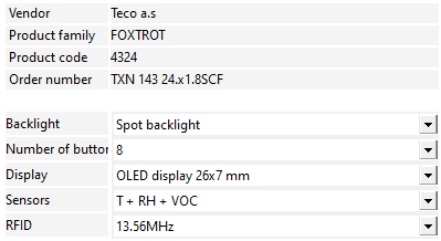
Fig. 7 Variant settings of the C-WS-0001R module
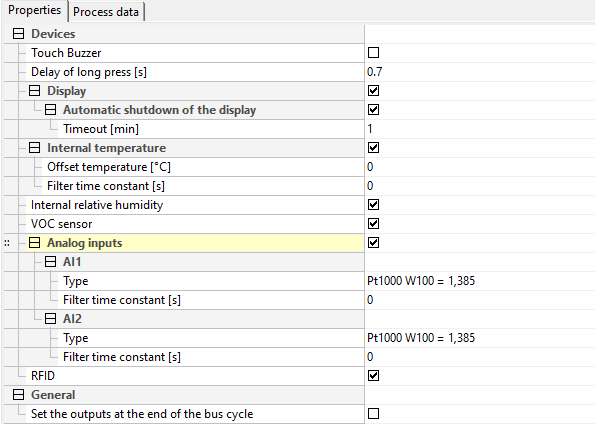
Fig. 8 Module configuration dialog in the I/O Configurator
Sound response to press
Option to turn on the sound response to the button press.
Long press delay
For buttons, the module directly evaluates short and long presses on individual inputs. By entering a value, you can set a time delay after which activation of the DI binary input will be signaled as a long press (PRESS). Activation of a binary input shorter than this specified value will be signaled as a short press (CLICK). The delay value (Tpress) is entered in the range of 0.1÷2.5s.
Fig. 9 Evaluation of short / long press
Types of AI input
For temperature sensors, the value is transmitted in °C (with a resolution of 0.1°C), for the general resistance range of 100kΩ in kΩ (with a resolution of 10Ω) and for the voltage range in mV.
| Input type | Measuring range |
|---|---|
| Pt1000, W100 1,385 | -90 ~ 320°C |
| Pt1000, W100 1,391 | -90 ~ 320°C |
| Ni1000, W100 1,617 | -60 ~ 200°C |
| Ni1000, W100 1,500 | -60 ~ 200°C |
| NTC 12k | -40 ~ 125°C |
| KTY 81-121 | -55 ~ 125°C |
| 0V100k | 0 - 100kΩ |
| 0 - 2V | 0 - 2V |
Tab. 1 Parameters of analog inputs
AI input filtering, temperature filtering
By entering a non-zero value of the time constant, the 1st order digital filter is activated. The filter is given by the relation
yt = (yt - 1·τ + x)/(τ + 1)
- x - the current value of the analog input
- yt - output
- yt - 1 - last output
- τ - time constant of the 1st order filter
The value of the filtering time constant is entered in the range 1÷254 and represents a time constant in the range 1s÷254s (the value 255 is intended for service purposes).
Temperature offset
Correction offset of the internal thermometer, by which the measured temperature of the internal thermometer will be adjusted.
The structure of the transmitted data
The module contains a total of 6 devices. Individual devices are included in the structure of the transmitted data, which is visible from the I/O Settings panel in the Mosaic environment.
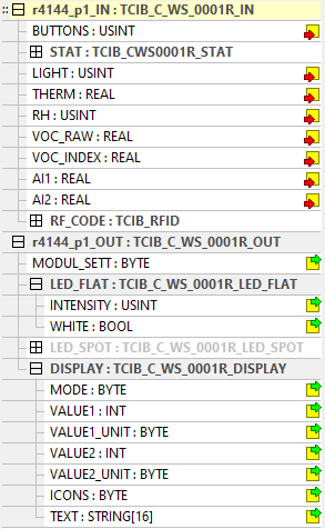
Fig. 10 The structure of the transmitted data for the I/O Configurator
Input data
|
BUTTONS
|
STAT
|
LIGHT
|
THERM
|
RH
|
VOC_RAW
|
VOC_INDEX
|
AI1 | AI2 | RF_CODE |
BUTTONS - button press (byte type)
|
-
|
-
|
CLICK
|
PRESS
|
BUTT
|
||||
| Bit |
.7
|
.6
|
.5
|
.4
|
.3
|
.2
|
.1
|
.0
|
- BUTT - button is pressed(1 - 8)
- PRESS - long press(do log. 1)
- CLICK - short press(do log. 1)
STAT - status of the analog inputs
| VLDVR | OUFVR | VLDR | OUFR | VLDT | OUFT | VLDL | OUFL | |
| Bit |
.7
|
.6
|
.5
|
.4
|
.3
|
.2
|
.1
|
.0
|
| - | - | VLD2 | OUF2 | VLD1 | OUF1 | VLDVI | OUFVI | |
| Bit |
.15
|
.14
|
.13
|
.12
|
.11
|
.10
|
.9
|
.8
|
- OUFL - overflow/underflow of the light intensity sensor range
- VLDL - the validity of the measurement of the light intensity sensor
- OUFT - overflow/underflow of the internal thermometer range
- VLDT - the validity of the measurement of the internal thermometer
- OUFR - overflow/underflow of the internal humidity sensor range
- VLDR - the validity of the measurement of the internal humidity sensor
- OUFVR - overflow/underflow of VOC sensor range
- VLDVR - the validity of the VOC sensor measurement
- OUFVI - overflow/underflow of the calculated VOC value
- VLDVI - the validity of the measurement of the converted VOC value
- OUF1 - overflow/underflow range of input AI1
- VLD1 - validity of AI1 input rate
- OUF2 - range overflow/underflow
- VLD2 - the validity of the input measure AI2
LIGHT - light intensity sensor value (usint type) [%]
THERM - internal thermometer value (real type) [°C]
RH - relative humidity value (usint type) [%]
VOC_RAW - measured VOC value 0-65535 (real type)
VOC_INDEX - converted VOC value 0-500 (real type)
AI1 - value of analog input 1 (type real) [°C],[kΩ],[mV]
AI2 - value of analog input 2 (real type) [°C],[kΩ],[mV]
RF_CODE - RFID code (8x byte type)
Output data
|
MODUL_SETT
|
LED_FLAT
|
LED_SPOT
|
DISPLAY
|
MODUL_SETT - module settings (byte type)
| - | - | BUZZ | BACKL_INT | BACKL | ||||
| Bit |
.7
|
.6
|
.5
|
.4
|
.3
|
.2
|
.1
|
.0
|
- BACKL - turning on the display backlight
- BACKL_INT - display backlight intensity setting, 0 - 10 = 0 -100%, with a step of 10%
- BUZZ - turning on the sound cue
LED_FLAT.INTENSITY - intensity of the white backlight of the buttons (usint type), 0 - 10 = 0 - 100%, with a step of 10%
LED_FLAT.WHITE - turning on the white backlight of the buttons (bool type)
LED_SPOT.INTENSITY - intensity of the color backlight of the buttons (usint type), 0 - 10 = 0 - 100%, with a step of 10%
LED_SPOT.GREENx - turning on the green signaling LED backlight (8x bool type)
LED_SPOT.REDx - switching on the red signaling LED backlight (8x bool type)
DISPLAY.MODE - display mode (byte type)
| - | - | F_VALUE2 | F_VALUE1 | F_ICONS | LAYOUT | |||
| Bit |
.7
|
.6
|
.5
|
.4
|
.3
|
.2
|
.1
|
.0
|
- LAYOUT - graphic display layout
- 0 - see picture of the layout of the dipler, variant a)
- 1 - see picture of the layout of the dipler, variant b)
- 2 - see picture of the layout of the diple, variant c)
- 3 - see picture of the layout of the diple, variant d)
- F_ICONS - flashing of the ICONS icon on the display
- F_VALUE1 - flashing value VALUE1 on the display
- F_VALUE2 - flashing value VALUE2 on the display
DISPLAY.VALUE1 - displayed value 1 on the display (type int)
DISPLAY.VALUE1_UNIT - value data type 1 (byte type)
0 - nic
1 - °C without decimal place (23 °C)
2 - °C with 1 decimal place (23.9 °C)
3 - °F without decimal place (23 °F)
4 - °F with 1 decimal place (23.9 °F)
5 - % without decimal place (23 %)
6 - ppm without decimal place (239 ppm)
7 - time (12:34)
8 - time + am (08:00 am)
9 - time + pm (08:00 pm)
DISPLAY.VALUE2 - displayed value 2 on the display (type int)
DISPLAY.VALUE2_UNIT - value data type 2 (byte type) value same as for VALUE1_UNIT
DISPLAY.ICONS - code of displayed icon (byte type)
DISPLAY.TEXT - text (string type [16])
 English