
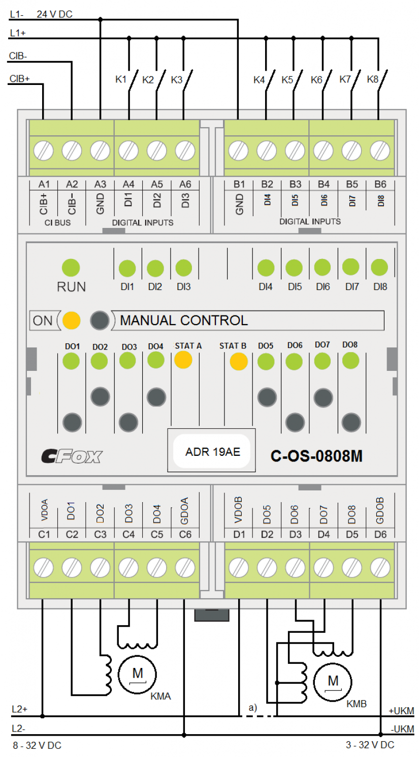
The module contains 8 binary inputs and 8 transistor outputs. The outputs are primarily intended for direct control of up to two stepper motors. Alternatively, the transistor outputs can be used as standard binary outputs, or it is possible to activate the output pulse width modulation (PWM) on the outputs.
The states of the individual inputs / outputs are indicated by indication LEDs.
The individual outputs allow local manual control by buttons on the module.
|
Binary inputs |
|
| Number | 8 (in group 3 + 5) |
| Input voltage for log.0 | -5 ÷ +5 VDC |
| Input voltage for log.1 | +15 ÷ +30 VDC |
| Input current for log.1 | 5 mA (at 24V) |
| Switch-on / switch-off delay | 5ms |
|
Binary outputs |
|
| Number | 8 (in group 4 + 4) |
| Output functions1) | 8x binary outputs / 2x stepper motor control / 8x PWM output3) |
| Operation mode2) | bipolar / unipolar |
| Switching voltage | 8 ÷ 32 VDC (see voltage L2 in the figure) |
| Switched output current | max. 2A |
| Switching group current | < 6A (at an ambient temperature of 25 ° C)
< 4A (at an ambient temperature of 50 ° C) |
| Bipolar mode
- type of output element - residual current - on / off time - short circuit protection |
(see KMA connection in the figure)
half H bridge max. 2mA typ. 1,6 / 0,6 us yes |
| Unipolar mode
- type of output element - residual current - on / off time - short circuit protection - voltage for winding step. engine |
(see KMB connection in the figure)
open collector max. 0,1mA typ. 20 / 20 us no 3 ÷ 32 VDC (see UKM voltage in figure) |
|
Operating and installation conditions |
|
| Operating temperature | -10 ÷ +55 °C |
| Storage temperature | -25 ÷ +70 °C |
| Degree of IP protection IEC 529 | IP20B |
| Overvoltage category | II (according to ČSN EN 60664) |
| Degree of pollution | 1 (according to ČSN EN 60664) |
| Working position | Vertical |
| Installation | On DIN rail |
| Connection terminals | Screw, removable |
| Wire cross section | Max. 2,5 mm2 |
|
1) possible combinations of functions see. chapter Configuration 2) outputs in DO function are fixed to unipolar mode, outputs in stepper motor function and PWM outputs have configuration selectable mode, Within one group of outputs (4 + 4) the mode must be the same for all outputs. 3) 8 PWM outputs are supported from FW v.1.2 (in groups 2 + 2 + 4). For lower versions the FW module supports only 2 PWM outputs |
|
|
Power supply |
|
| Power and communication | 24 V (27 V) from CIB bus |
| Max. consumption | 85 mA |
| Size and weight | |
| Dimensions | 70 x 90 x 63 mm |
| Weight | 142 g |
Configuration of stepper actuators
Driving mode
The step actuator can be controlled in several modes. The states of the outputs are described in the following tables.
- unipolar single-phase control with full step
- unipolar two-phase control with full step
- unipolar control with half step
- bipolar single-phase control with full step
- bipolar two-phase control with full step
- bipolar control with half step
Output settings for unipolar single-phase control with full step (mode 16)
|
Step |
Outputs |
|||
| DO1
DO5 |
DO2
DO6 |
DO3
DO7 |
DO4
DO8 |
|
| 1 | 1 | 0 | 0 | 0 |
| 2 | 0 | 1 | 0 | 0 |
| 3 | 0 | 0 | 1 | 0 |
| 4 | 0 | 0 | 0 | 1 |
Output settings for unipolar two-phase control with full step (mode 20)
|
Step |
Outputs |
|||
| DO1
DO5 |
DO2
DO6 |
DO3
DO7 |
DO4
DO8 |
|
| 1 | 1 | 0 | 0 | 0 |
| 2 | 0 | 1 | 0 | 0 |
| 3 | 0 | 0 | 1 | 0 |
| 4 | 0 | 0 | 0 | 1 |
Output settings for unipolar control with half step (mode 32)
|
Step |
Outputs |
|||
| DO1
DO5 |
DO2
DO6 |
DO3
DO7 |
DO4
DO8 |
|
| 1 | 1 | 0 | 0 | 0 |
| 2 | 1 | 1 | 0 | 0 |
| 3 | 0 | 1 | 0 | 0 |
| 4 | 0 | 1 | 1 | 0 |
| 5 | 0 | 0 | 1 | 0 |
| 6 | 0 | 0 | 1 | 1 |
| 7 | 0 | 0 | 0 | 1 |
| 8 | 1 | 0 | 0 | 1 |
Output settings for bipolar single-phase control with full step (mode 17)
|
Step |
Outputs |
|||
| DO1
DO5 |
DO2
DO6 |
DO3
DO7 |
DO4
DO8 |
|
| 1 | + | – | – | – |
| 2 | – | + | - | – |
| 3 | – | - | + | – |
| 4 | – | – | – | + |
Output settings for bipolar two-phase control with full step (mode 21)
|
Step |
Outputs |
|||
| DO1
DO5 |
DO2
DO6 |
DO3
DO7 |
DO4
DO8 |
|
| 1 | + | + | - | – |
| 2 | – | + | + | – |
| 3 | – | - | + | + |
| 4 | + | – | – | + |
Output settings for bipolar control with half step (mode 33)
|
Step |
Outputs |
|||
| DO1
DO5 |
DO2
DO6 |
DO3
DO7 |
DO4
DO8 |
|
| 1 | + | – | – | – |
| 2 | + | + | - | – |
| 3 | – | + | - | – |
| 4 | – | + | + | – |
| 5 | – | - | + | – |
| 6 | – | - | + | + |
| 7 | – | – | – | + |
| 8 | + | – | – | + |
Minimum speed
The minimum speed is the lowest speed at which the axis movement is initiated when accelerating from zero speed, or the movement is completed when the axis is braked to a stop. The speed can be set in the range 5 ÷ 10000 [pulse / s]. The set value can be changed with command (11).
Maximal speed
The maximum speed is the highest allowed speed that can be entered as a parameter of the motion command. The speed can be set in the range 5 ÷ 10000 [pulse / s].
Maximum acceleration
The maximum acceleration is the maximum allowed acceleration that can be entered as the operating acceleration. This value also serves as the default value for the operating acceleration. Acceleration can be set in the range 5 ÷ 240 [pulse / s2]. The set value of the operating acceleration can be changed with the command (12).
Maximum deceleration
The maximum deceleration is the maximum permitted deceleration that can be entered as the operating deceleration. This value serves as the default value for both the operating deceleration and the maximum deceleration for stopping the movement immediately. The deceleration can be set in the range 5 ÷ 240 [pulse / s2]. The values of both of these parameters can be changed independently of each other with the command (13 and 14).
Acceleration/deceleration ramps
This parameter can be used to set whether motor speed changes are to be made in steps (ramps are inactive) or continuously according to the entered acceleration / deceleration values (ramps are active). Ramp activation can be changed by command (9).
Configuration of PWM outputs
PWM outputs are configurable in groups (2 + 2) + 4. The setting of the period and control mode is common for the whole group, the setting of pulse activity is then selectable for each output separately.
If some outputs are configured as binary outputs and some as PWM outputs, the PWM outputs must have a unipolar control mode (according to the binary outputs).
Period of PWM outputs
The common period of PWM outputs can be entered in the range of 10 ÷ 1,000,000 [us] (100kHz ÷ 1Hz).
PWM output control mode
The common mode of PWM outputs can be selected in unipolar or bipolar mode.
The PWMn pulse is active
For each PWM output it is possible to set separately with which polarity we want to send pulses. If we select the variant in the log.1 level, then the level of the own pulse is log.1 and the resting level is log.0. If we select the variant in the log.0 level, the opposite is true.
Description of the behavior of the stepper actuator operators
The binary transistor outputs DOn can be used to control up to two stepper actuators. Drive A is controlled by four outputs DO1 ÷ DO4, drive B is controlled by four outputs DO5 ÷ DO8. The module sends signals for the winding of the stepper actuator to each of the four respective outputs. Each stepper actuator has its own input and output data structure (MCA, MCB), which is described in the previous chapter.
The outputs used to control the stepper actuator cannot be controlled as normal DO outputs at the same time, nor as PWM outputs.
Stepper motor axis movement
The stepper motor is controlled by four signals into which the corresponding sequence of output pulses is generated. The number of generated pulses determines the position of the axis, the frequency of the pulses then determines the speed of movement. Each movement with a specified path usually has three phases.
The first phase is the movement evenly accelerated. An axis that is at rest starts the movement in increments at the minimum traversing speed (parameter specified by the user in the configuration or command) and further increases the traversing speed evenly at the specified acceleration until it reaches the desired traversing speed.
The second phase consists of a uniform movement at a steady speed, which corresponds to the required speed of movement.
The third phase is the movement evenly slowed down. The axis evenly reduces the speed of movement at the specified deceleration to the minimum speed. After reaching the minimum speed, the movement is abruptly terminated.
If the movement is realized without acceleration / deceleration ramps, the first and third phases are skipped and the speed change then takes place in steps.

Fig. 3 Basic course of speed of movement in time
The movements are performed in two modes - speed and position. Speed mode is used for movements at a specified speed on an infinite path. It is therefore designed primarily for rotary axes. In addition to the speed of movement, the position mode also defines the path of movement.
The motion mode is tied to the command used. Commands 105 (continuous movement at the specified speed) and 108 (stop by operating deceleration) operate the axis in speed mode. Other motion commands operate the axis in position mode. Both sets of commands can be combined to switch from one mode of movement to another while moving.
Speed motion mode
If we want to operate the axis in speed mode, we use command 105 (continuous motion at the specified speed) to enter the motion, which defines only the target motion speed. The axis starts at the required speed and maintains this speed until a new speed is entered or an axis stop command is issued.
Reaching the specified speed is indicated by setting the INVEL bit in the MCSTAT variable in the input zone to 1. Axis movement is indicated by setting the MOVE bit in the MCSTAT variable to 1. When the movement is stopped, the MOVE bit is reset. The current direction of movement is indicated by the DIR bit in the MCSTAT variable (0 positive direction of movement, 1 negative direction of movement). The INVEL bit is reset automatically by writing another motion command.
In speed mode, you can change the speed and direction of movement while moving. The behavior of the axis and the indication of its status are shown in the following figures.

Fig. 4 Start moving in speed mode

Fig. 5 End of movement in speed mode

Fig. 6 Changing the speed of movement while maintaining the direction in speed mode

Fig. 7 Changing the speed of movement when changing direction in speed mode
In speed mode, command 108 also operates, which stops the axis immediately by operational deceleration, regardless of its current or target position.
A description of the behavior of these commands is given in the chapter Motion commands below.
Position mode of movement
Other motion commands are used to operate the axis in position mode, where in addition to the speed of movement, the path of motion is also entered. The movement then has the three phases described above and after the completion of the deceleration phase it stops exactly at the target position (see the following picture). This means that exactly as many pulses as are entered are sent during the entire movement.
Reaching the target position is indicated by setting the TRG bit in the MCSTAT variable in the input zone to 1. Axis movement is indicated by setting the MOVE bit in the MCSTAT variable to 1. When the movement is stopped, the MOVE bit is reset. The current direction of movement is indicated by the DIR bit in the MCSTAT variable (0 positive direction of movement, 1 negative direction of movement). The TRG bit is reset automatically by writing another motion command.

Fig. 8 Standard movement in position mode with commands 101 or 102
Because the motor speed is determined by the frequency of the pulses, the speed change is not completely smooth, unlike voltage control. Therefore, there may be some deviation in the calculation of the path required for the third phase of movement, ie deceleration. This deviation can be in the order of pulse units.
If the axis has already reached the minimum speed in the deceleration phase and the target position has not yet been reached, the target position is approached at the minimum speed. If the target position is reached before reaching the minimum speed, the movement is stopped immediately.
If we enter a path that is too short, the axis must start to decelerate before it reaches the specified speed. Such a movement then does not have a second phase (uniform movement), but passes from the acceleration phase directly to the deceleration phase (see the following figure).
In position mode, already entered movements can be changed immediately. The following movement commands are used to define them
101 - shift to target position (path defined by absolute target position)
102 - offset by the specified distance (path defined by relative offset)
A description of the behavior of these commands is given in the chapter Motion commands below.

Fig. 9 Shortened course of movement when entering a short path with commands 101 or 102
Simple positional movement
If the axis is at rest, then writing command 101 or 102 will cause an immediate start of the movement with the parameters given by this command. The behavior of the axis and the indication of its status are shown in the previous two figures.
Immediate change of positional movement
If the axis is in motion, then writing command 101 or 102 will cause an immediate change in motion with the parameters given by this new command. Speed changes take place according to the entered operating accelerations and decelerations.
Reaching the target position of the new movement is indicated by setting the TRG bit in the MCSTAT variable in the input zone to 1. Axis movement is indicated by setting the MOVE bit in the MCSTAT variable to 1. When the movement is stopped, the MOVE bit is reset. The current direction of movement is indicated by the DIR bit in the MCSTAT variable (0 positive direction of movement, 1 negative direction of movement).
The behavior of the axis and the indication of its status are shown in the following two figures.

Fig. 10 Example of double change of current movement while maintaining direction in position mode by commands 101 or 102 (originally planned trajectories are shown in dashed lines)

Fig. 11 Example of changing the current movement when changing direction in position mode with commands 101 or 102 (the originally planned trajectory is shown in dashed lines)